


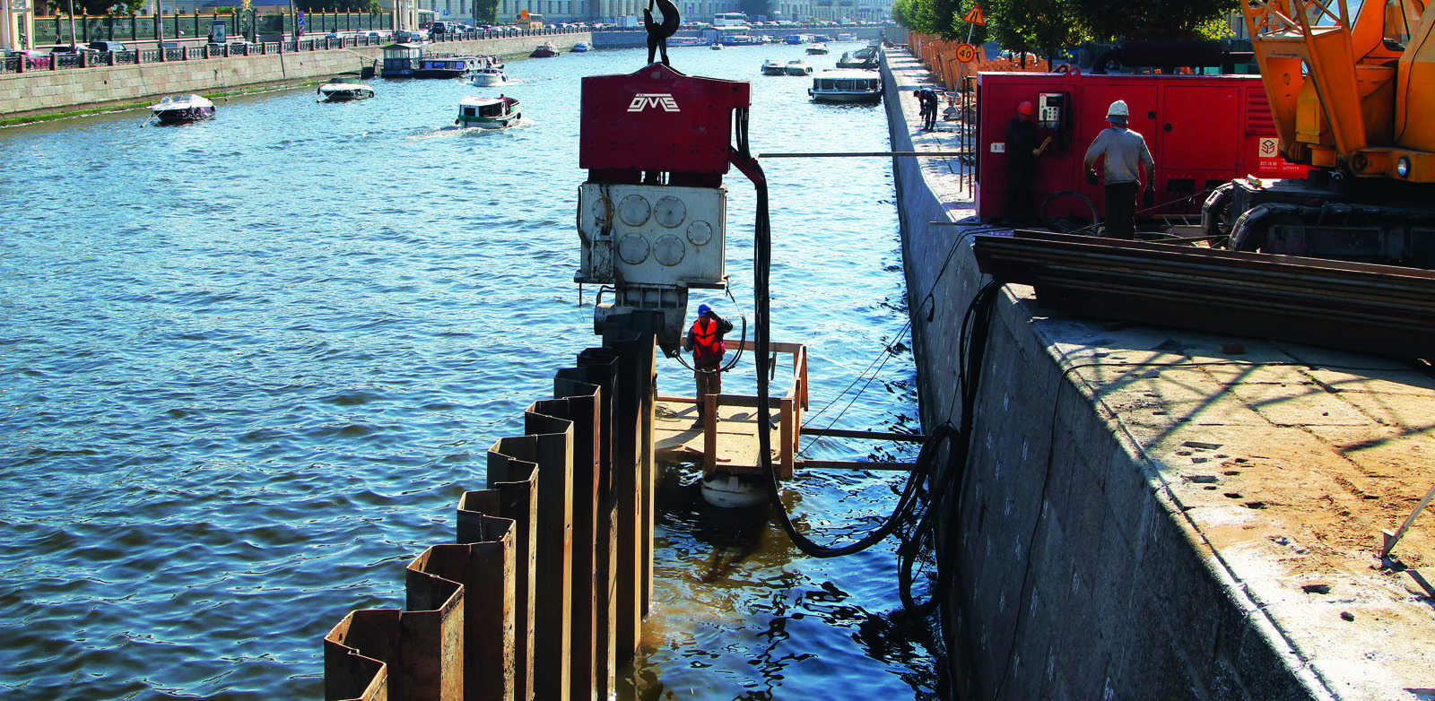
Resonance Free Vibro Hammers
Controlled Pile Driving in Vibration-Sensitive Areas
Pile driving and extraction in urban environments require more than sufficient driving force. Nearby buildings, historical structures, buried utilities, operating facilities and transport infrastructure can impose strict limits on ground vibration, noise, working space and equipment movement.
One of the most critical stages is the transition through start-up and shutdown. A conventional vibratory system may pass through frequencies that interact with the natural response of the soil-pile system. This transition can temporarily increase vibration transmission to the surrounding ground.
OMS addresses this operational challenge with its resonance-free variable moment vibro hammers. The VM Series includes both crane-suspended and excavator-mounted configurations, allowing the equipment arrangement to be selected according to the pile, site layout, carrier availability and lifting requirements.
It is important to clarify that “resonance-free” does not mean that the hammer produces no vibration while driving or extracting a pile. The term refers specifically to controlling the eccentric moment during start-up and shutdown so that the system does not generate significant vibration while passing through the resonance range.
OMS resonance-free vibro hammers provide two distinct installation approaches for low-vibration pile driving and extraction. The crane-suspended SVR VM Series supports projects requiring dedicated lifting and hydraulic power systems, while the excavator-mounted OVR VM Series provides carrier mobility and integrated site operation.
Both systems use variable moment technology to control the start-up and shutdown stages. Effective results, however, depend on correct model selection, carrier compatibility, hydraulic supply, clamp configuration, pile properties, soil conditions and vibration-monitoring requirements.
Advantages
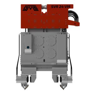
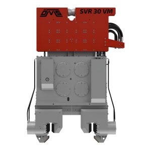
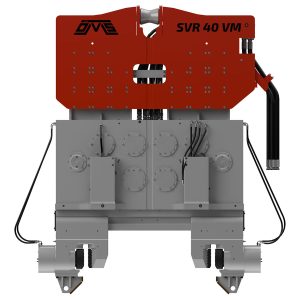
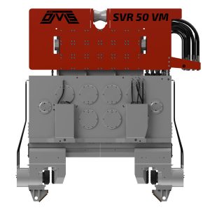
Crane-Suspended SVR VM Vibro Hammers
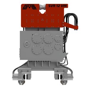
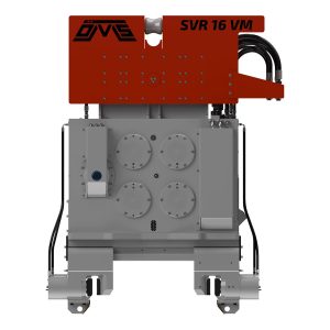
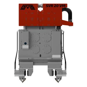
Technical Specifications
| Technical Specifications | 8 VM | 12 VM | 16 VM | 20 VM | 24 VM | 30 VM | 40 VM | 50 VM |
|---|---|---|---|---|---|---|---|---|
| Eccentric Moment (kgm) | 0 – 8 | 0 – 12 | 0 – 16 | 0 – 20 | 0 – 24 | 0 – 30 | 0 – 40 | 0 – 50 |
| Centrifugal Force (kN) Max. | 464 | 698 | 934 | 1166 | 1370 | 1746 | 2348 | 2923 |
| Power (kW) | 103 | 211 | 287 | 292 | 394 | 448 | 548 | 805 |
| Weight and Dimensions | ||||||||
| Total Weight W/O Clamp (kg) | 1857 | 2570 | 3650 | 4280 | 4523 | 5700 | 7603 | 8900 |
| Length / L1 (mm) | 1490 | 1695 | 1925 | 2060 | 2060 | 2210 | 2797 | 3135 |
| Height / H1 (mm) | 1566 | 1660 | 2002 | 2115 | 2115 | 2460 | 2616 | 2450 |
| Width / W1 (mm) | 300 | 301 | 321 | 388 | 388 | 388 | 384 | 388 |
| Technical Specifications | 8 VM | 12 VM | 16 VM | 20 VM | 24 VM | 30 VM | 40 VM | 50 VM |
|---|---|---|---|---|---|---|---|---|
| Eccentric Moment (in.lbs) | 0 – 694 | 0 – 1042 | 0 – 1389 | 0 – 1736 | 0 – 2083 | 0 – 2604 | 0 – 3472 | 0 – 4340 |
| Centrifugal Force Max. (tons) | 52 | 78 | 105 | 131 | 154 | 196 | 264 | 329 |
| Power (HP) | 138 | 283 | 385 | 392 | 528 | 601 | 735 | 1080 |
| Weight and Dimensions | ||||||||
| Total Weight W/O Clamp (lbs) | 4094 | 5666 | 8047 | 9436 | 9972 | 12566 | 16762 | 19621 |
| Length / L1 (in) | 59 | 67 | 76 | 81 | 81 | 87 | 110 | 123 |
| Height / H1 (in) | 62 | 65 | 79 | 83 | 83 | 97 | 103 | 96 |
| Width / W1 (in) | 12 | 12 | 13 | 15 | 15 | 15 | 15 | 15 |
How Phase Shifter (Variable Mechanism) Works in a Vibratory Hammer?
A vibratory hammer generates cyclic force through rotating eccentric masses inside its vibration housing. This force transfers through the hydraulic clamp to the pile, reducing resistance along the pile-soil interface and supporting penetration or extraction.
In an OMS variable moment vibro hammer, a phase shifter mechanism changes the relative position of the eccentric masses. During start-up, the eccentric masses remain in a balanced position while the system accelerates. After the hammer reaches its operating frequency, the mechanism changes their relative position and develops the required eccentric moment.
During shutdown, the sequence is reversed. The eccentric moment is reduced before the rotational speed passes through the critical frequency range. This operating principle provides a resonance-free start and stop while allowing the amplitude and eccentric moment to be adjusted between their minimum and maximum settings.
The result is better control over how vibratory energy enters the pile-soil system, especially during the transition stages that require close vibration management. The OMS VM product range also uses high-capacity anti-vibration mounts to limit vibration and sound transmission through the suspended or carrier-connected parts of the system.
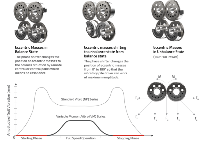
Eccentric Masses in Balance State
The phase shifter changes the position of eccentric masses to the balance situation by remote control or control panel which means no resonance.
Eccentric masses shifting to unbalance state from balance state
The phase shifter changes the position of eccentric masses from 0° to 180° so that the vibratory pile driver can work at maximum amplitude.
Eccentric Masses in Unbalance State
(180° Full Power)
The crane-suspended SVR VM Series is designed for variable moment pile driving and extraction operations where the project requires a crane-based handling system.
In this configuration, the crane supports and positions the complete vibro hammer assembly. A separate OMS hydraulic power pack supplies the hydraulic energy required by the hammer and clamp system. Depending on the pile profile, the system can be equipped with an appropriate sheet-pile or casing clamp.
OMS Hydraulic Power Pack
SVR VM vibro hammers operate with matched OMS hydraulic power packs. The power pack supplies the hydraulic flow and power required by the vibration system and auxiliary clamp circuit.
OMS power units incorporate control systems that allow operating parameters and system status to be monitored. Depending on the configuration, operation can be managed through the touchscreen panel or wired and wireless remote-control options.
The recommended power pack depends on the selected SVR VM model:
| SVR VM model | Recommended OMS power pack |
| SVR 8 VM | PP 218 |
| SVR 12 VM | PP 320 |
| SVR 16 VM | PP 422 |
| SVR 20 VM | PP 536 |
| SVR 24 VM | PP 536 |
| SVR 30 VM | PP 768 |
| SVR 40 VM | PP 1072 |
| SVR50 VM | PP 1536 |
Important: These are catalogue pairings. Final configuration must also account for hose arrangement, project conditions and any application-specific auxiliary requirements.
Hydraulic Clamps for Pipe Piles
OMS KCN Series hydraulic clamps are designed for tube and casing applications.
Depending on the pipe diameter and SVR VM model, double or multiple clamp configurations may be used. The catalogue pairings for the specified range are:
| SVR VM model | Recommended Clamps for Casing |
| SVR 8 VM | KCN 45 × 2 |
| SVR 12 VM | KCN 45 × 2 |
| SVR 16 VM | KCN 60 × 2 |
| SVR 20 VM | KCN 90 × 2 |
| SVR 24 VM | KCN 90 × 2 |
| SVR 30 VM | KCN 120 × 2 |
| SVR 40 VM | KCN 185 × 2 |
| SVR 50 VM | KCN 185 × 2 |
Pipe diameter, wall thickness, lifting method and clamp beam design must be verified before confirming the configuration.
Hydraulic Clamps for Sheet Piles
OMS SCN Series hydraulic clamps provide the connection between the vibro hammer and the sheet pile. The fixed and movable jaw arrangement applies hydraulic clamping force to the pile, allowing vibration and extraction force to be transmitted through the clamped section.
The standard catalogue pairings include:
| SVR VM model | Recommended Clamps for Sheet | ||
| SVR 8 VM | SCN 60 | ||
| SVR 12 VM | SCN 100 | ||
| SVR 16 VM | SCN 120 | ||
| SVR 20 VM | SCN 165 | ||
| SVR 24 VM | SCN 165 | ||
| SVR 30 VM | SCN 200 | ||
| SVR 40 VM | SCN 350 | ||
| SVR 50 VM | SCN 350 | ||
The complete clamp range can be reviewed on the OMS hydraulic clamps page.
Where the Crane-Suspended Configuration Fits
A crane-suspended resonance-free vibro hammer may be suitable when:
- Long or heavy piles require crane handling.
- The project includes sheet piles, tubular piles, casings or other compatible pile sections.
- Driving and extraction take place at considerable reach or depth.
- The lifting plan already incorporates a crawler crane or another suitable crane.
- A dedicated hydraulic power pack is required for the selected hammer.
- The project needs adjustable eccentric moment for changing ground conditions or vibration limits.
The SVR VM range includes different capacities for varying pile sizes and project requirements. However, model selection should not be based only on pile weight or length. The evaluation must also consider soil resistance, pile section, penetration depth, extraction resistance, required pulling force, clamp configuration and the available crane capacity. The selected crane must account for the total suspended load, including the vibro hammer, suppressor, hydraulic clamp, pile, lifting accessories and dynamic operational effects.
Excavator-Mounted OVR VM Vibro Hammers
Technical Specifications
| Technical Specifications | OVR 80 VM | OVR 120 VM |
|---|---|---|
| Eccentric Moment (kgm) | 0 – 8 | 0 – 12 |
| Centrifugal Force (kN) | 464 | 698 |
| Power (kW) | 103 | 193 |
| Weight and Dimensions | ||
| Total Weight W/O Clamp (kg) | 1650 | 2160 |
| Length / L1 (mm) | 1280 | 1566 |
| Height / H1 (mm) | 1680 | 1614 |
| Width / W1 (mm) | 471 | 511 |
| Technical Specifications | OVR 80 VM | OVR 120 VM |
|---|---|---|
| Eccentric Moment (in.lbs) | 0 – 694 | 0 – 1042 |
| Centrifugal Force (tons) | 52 | 78 |
| Power (hP) | 138 | 259 |
| Weight and Dimensions | ||
| Total Weight W/O Clamp (lbs) | 3637 | 4762 |
| Length / L1 (in) | 50 | 62 |
| Height / H1 (in) | 66 | 64 |
| Width / W1 (mm) | 10 | 12 |
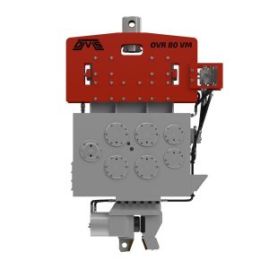
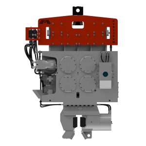
The OVR VM Series combines resonance-free variable moment technology with an excavator-mounted configuration. The hammer connects to the excavator through a compatible connection bracket and receives hydraulic power from the excavator.
This arrangement allows the excavator operator to position the hammer, grip the pile and perform the driving or extraction cycle from the carrier. OMS states that its OVR excavator-mounted vibro hammers can be connected without requiring modifications to the excavator, subject to correct hydraulic and mechanical compatibility.
Where the Excavator-Mounted Configuration Fits
An excavator-mounted resonance-free vibro hammer may be suitable when:
- The working area favours a mobile carrier rather than a crane and separate power pack.
- The project involves repeated pile positioning and short operating cycles.
- Space, access or equipment mobilisation is restricted.
- The excavator provides the required hydraulic pressure and oil flow.
- The carrier has sufficient working weight, lifting capacity and hydraulic cooling performance.
- The pile length and handling method remain within the excavator’s safe working envelope.
The OVR VM Series supports controlled pile driving and extraction while offering practical movement between working points. It can therefore be considered for urban retaining structures, temporary works and infrastructure projects where frequent repositioning is necessary.
Carrier selection remains a critical engineering step. Excavator weight alone does not confirm compatibility. Hydraulic flow, operating pressure, return-line conditions, auxiliary circuit configuration, cooling capacity, connection bracket design, boom geometry and lifting chart must all be verified.
Crane-Suspended and Excavator-Mounted Systems Compared
| Selection factor | Crane-suspended SVR VM | Excavator-mounted OVR VM |
| Primary carrier | Suitable crane | Compatible hydraulic excavator |
| Hydraulic supply | Dedicated OMS hydraulic power pack | Excavator hydraulic system |
| Typical strength | Handling long or heavy piles and larger suspended systems | Mobility and efficient repositioning within the site |
| Pile positioning | Managed through crane lifting operations | Controlled through excavator boom and attachment |
| Site arrangement | Requires crane operating and lifting area | Requires suitable excavator access and stable working platform |
| Main compatibility check | Crane capacity, lifting plan, power pack and clamp | Carrier weight, hydraulic circuit, cooling and attachment |
| Shared technology | Adjustable eccentric moment and resonance-free start/stop | Adjustable eccentric moment and resonance-free start/stop |
Neither mounting type is automatically the better option. The correct configuration depends on the complete installation process, not only the vibro hammer.
System Components and Configuration
Hydraulic Power Supply
Crane-suspended VM hammers operate with a matched OMS hydraulic power pack. Power pack selection must correspond to the hammer’s required hydraulic flow, power demand, circuit configuration and control functions.
OMS power units can include touchscreen and remote-control functions for monitoring and controlling the hydraulic system. Depending on the configuration, control functions may include engine speed, amplitude or moment adjustment, vibration start and stop, clamp operation and safety controls.
For excavator-mounted VM hammers, the excavator becomes the hydraulic power source. Its auxiliary hydraulic circuit must therefore be evaluated as part of the complete hammer-carrier system.
Hydraulic Clamp Selection
The clamp creates the mechanical connection through which vibratory force and pulling load transfer to the pile. OMS offers different hydraulic clamp systems for different pile profiles:
- SCN Series for sheet piles
- KCN Series for tubular piles and casings
- ACN Series for timber piles
Correct clamp selection depends on pile geometry, wall thickness, contact surface, required clamping force and operating load. The gripping surfaces must engage the pile correctly before vibration begins. Inadequate seating, worn jaws or an unsuitable clamp can reduce energy transfer and increase the risk of pile slippage or local deformation.
Application Near Sensitive Structures
Resonance-free technology is particularly relevant to pile driving and extraction near historical buildings, occupied structures, industrial facilities and buried services. Nevertheless, the hammer is only one part of the vibration-management strategy.
A controlled urban operation should generally include:
- Review of the pile type, depth and expected soil resistance.
- Identification of nearby structures and vibration-sensitive assets.
- Definition of project-specific vibration limits.
- Pre-work condition surveys where required.
- Suitable vibration monitoring locations and instruments.
- A documented response procedure if trigger levels are reached.
- Controlled adjustment of eccentric moment during trial operations.
- Continuous review of penetration or extraction behaviour.
Ground vibration depends on the hammer setting, pile-soil interaction, distance, stratigraphy and the dynamic characteristics of nearby structures. Therefore, the same machine setting can produce different results on different sites. Project-specific limits and monitoring plans should be established by the responsible engineering team.
Equipment Selection Criteria
The following decision sequence provides a general selection framework:
- Define the pile
Confirm the pile profile, dimensions, length, weight, material, installation depth and whether the operation involves driving, extraction or both. - Review ground conditions
Assess the soil layers, groundwater conditions, expected toe resistance, shaft resistance and possible obstructions. - Establish environmental constraints
Identify nearby structures, allowable vibration levels, noise restrictions, operating hours and access limitations. - Select the mounting configuration
Choose between a crane-suspended SVR VM and an excavator-mounted OVR VM according to pile handling, carrier availability, reach, mobility and site layout. - Match the hydraulic system
For an SVR VM system, select a compatible OMS power pack. For an OVR VM system, verify the excavator’s hydraulic and cooling capacity. - Select the clamp
Match the hydraulic clamp to the pile profile and operating load. Confirm that the clamp can safely transfer both vibratory and extraction forces. - Confirm the complete operating envelope
Review the carrier, hammer, clamp, pile, lifting accessories, hoses, working platform and monitoring procedure as one integrated system.
Frequently Asked Questions
The phase shifter controls the relative position of the eccentric masses. It keeps the eccentric moment balanced during acceleration and reduces it before deceleration, limiting vibration generation while passing through the resonance range.
No. Vibration is required during the driving or extraction phase. “Resonance-free” describes the controlled start and stop sequence, not the elimination of operational vibration.
Yes. Crane-suspended SVR VM and excavator-mounted OVR VM hammers can support pile driving and extraction when correctly matched to the pile, clamp, ground conditions and carrier.
The choice depends on the project. An excavator-mounted system can offer mobility and fast repositioning, while a crane-suspended system can support longer or heavier piles and dedicated hydraulic power. Site access, pile handling and carrier capacity determine the appropriate configuration.
Where nearby structures or project specifications impose vibration limits, monitoring may still be required. Resonance-free technology supports vibration management but does not replace a project-specific monitoring and response plan.
Clamp selection depends on pile profile, dimensions, contact geometry and required load transfer. OMS offers SCN clamps for sheet piles, KCN clamps for tubular piles and casings, and ACN clamps for timber piles.
For project-specific equipment selection, send the pile dimensions, soil information, target depth, site restrictions and available carrier details to the OMS Vibro technical team.