


Wick Driver
Accelerating Consolidation in Soft and Cohesive Soils
Soft and cohesive soil layers create significant challenges for infrastructure and foundation projects. Their low permeability can restrict groundwater movement, resulting in extended consolidation periods, residual settlement and uncertainty in the construction schedule.
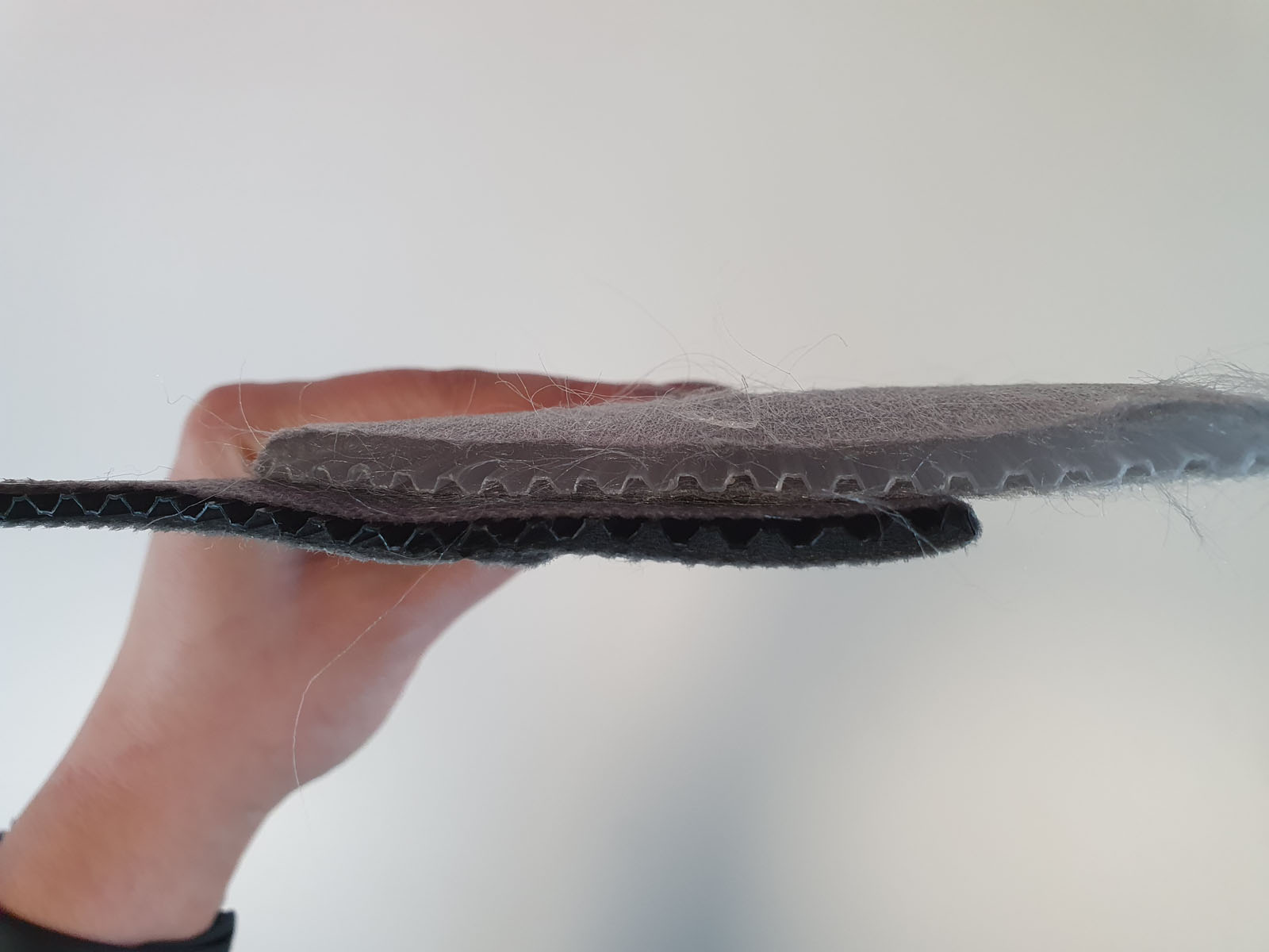
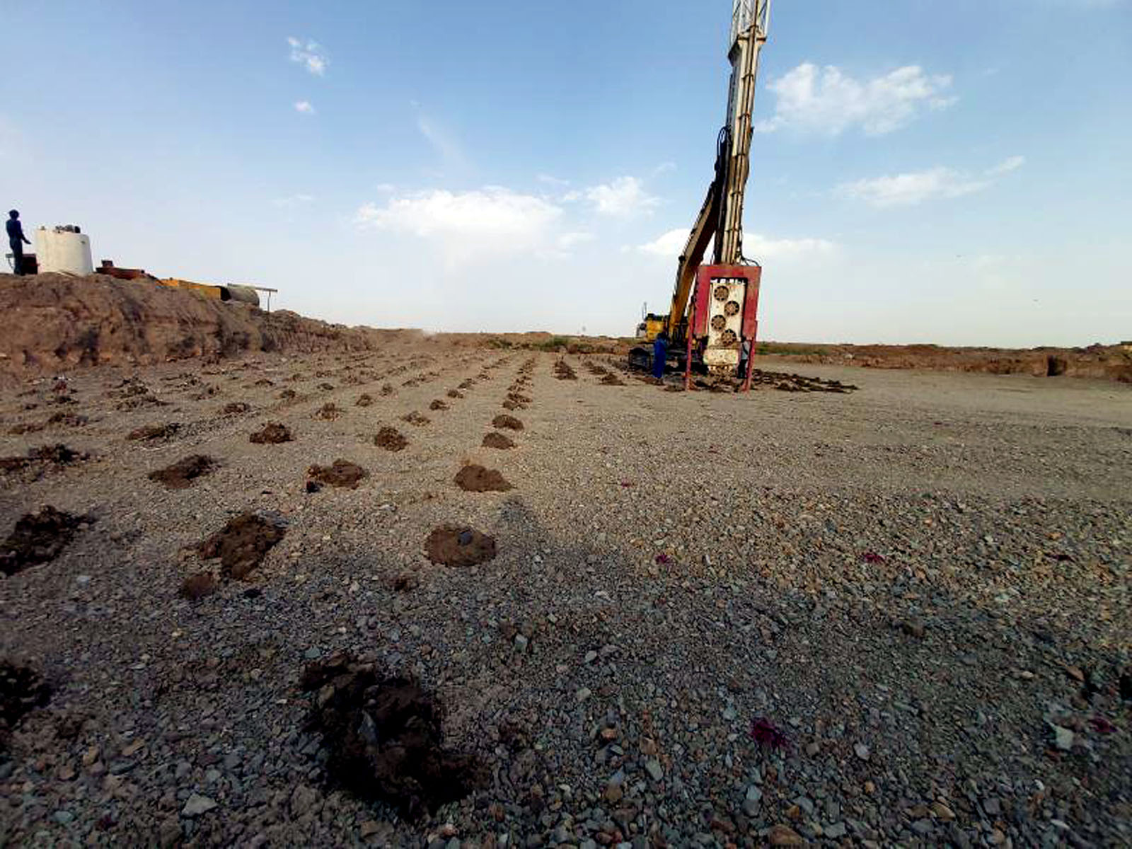
Prefabricated vertical drains, also known as PVDs or wick drains, reduce the drainage path that pore water must travel. When installed according to the project-specific pattern and combined with the required surcharge loading, they create vertical drainage routes through which groundwater can rise toward the drainage blanket.
However, the efficiency of the process depends on more than the drain material. Penetration resistance, installation depth, drain spacing, mast stability, mandrel alignment and extraction control directly affect installation quality.
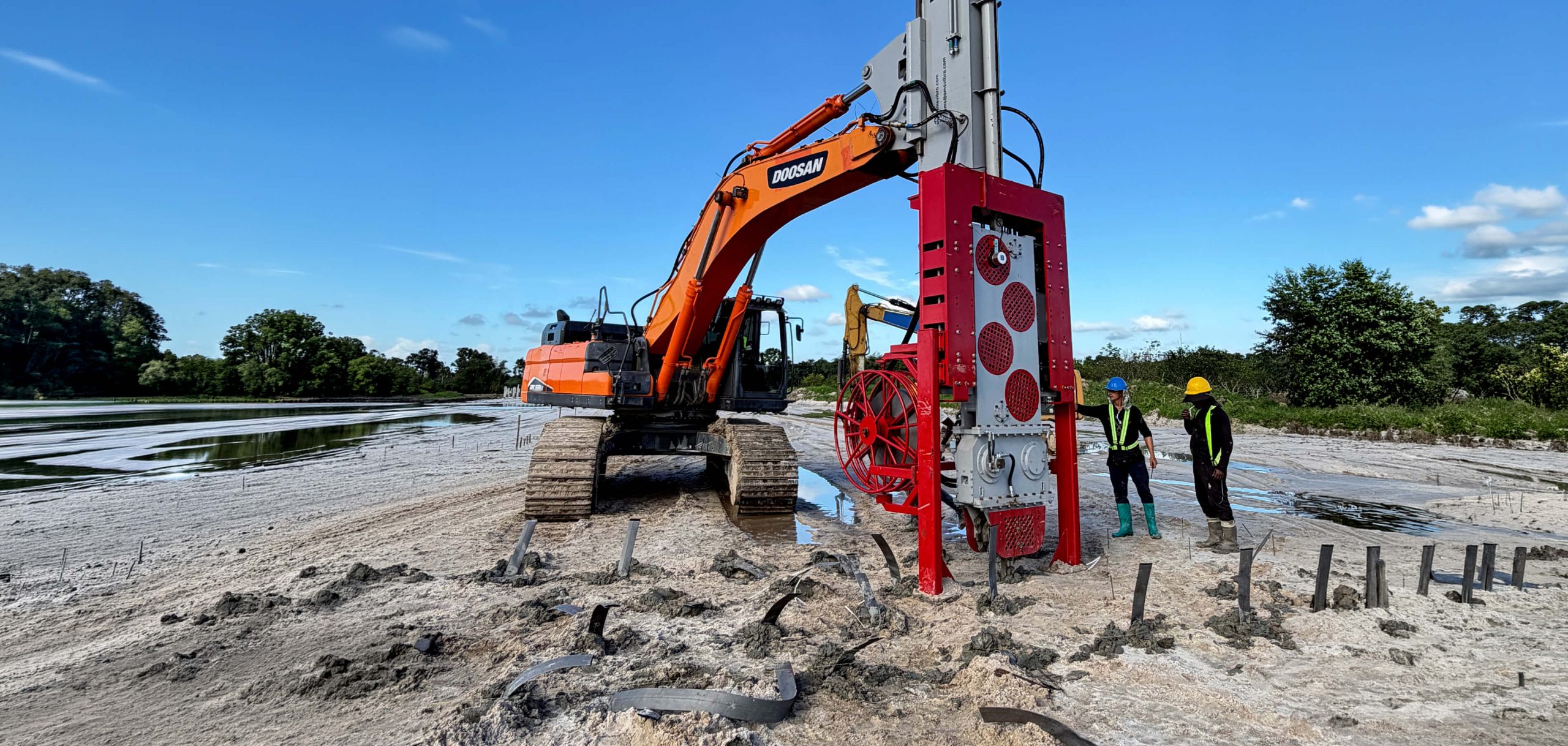
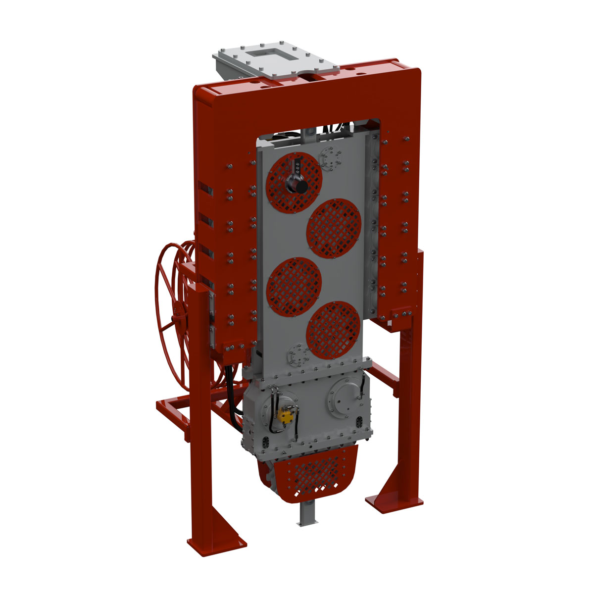
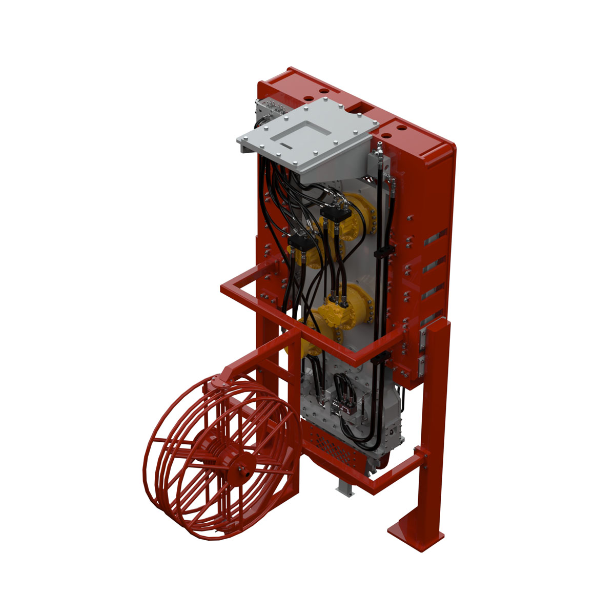
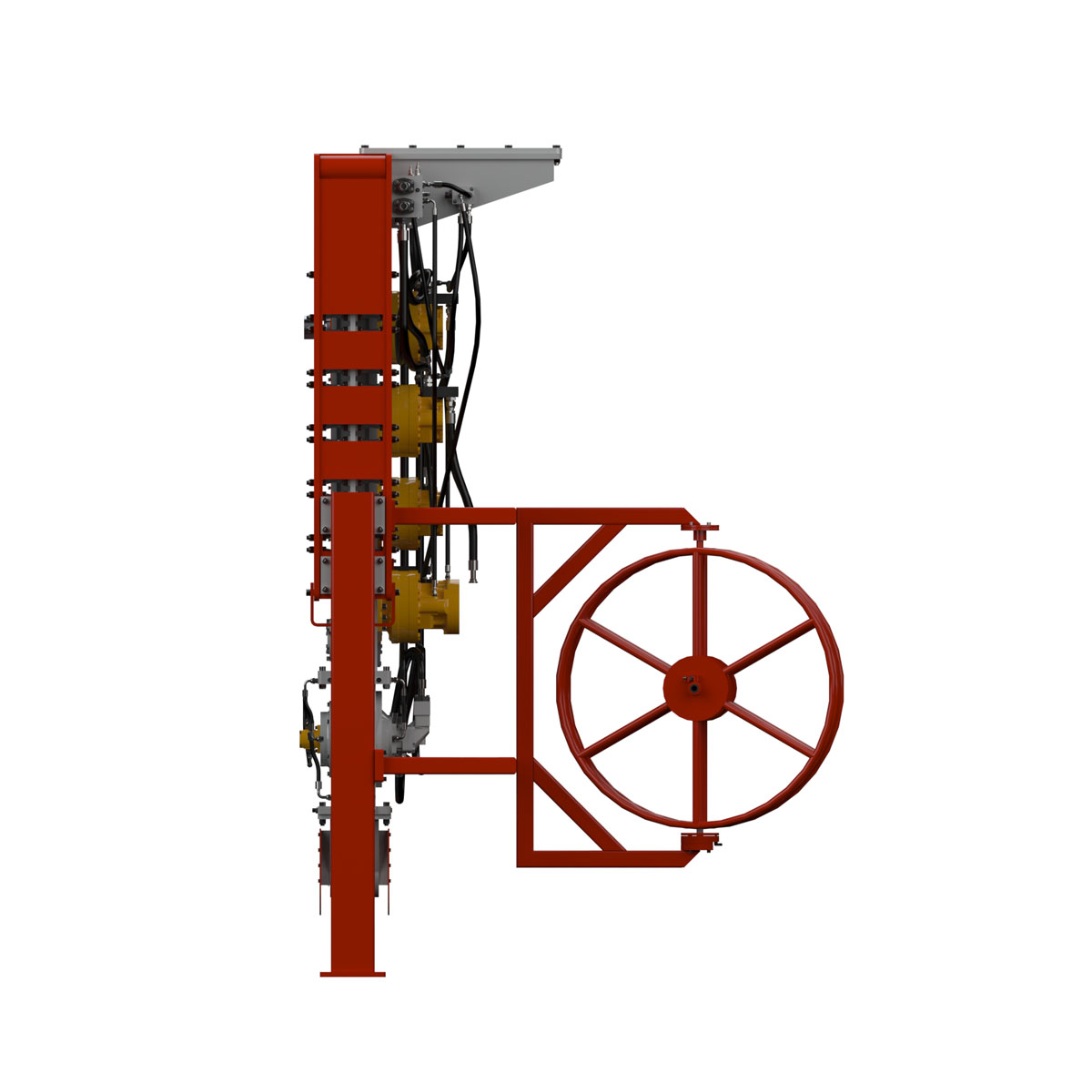
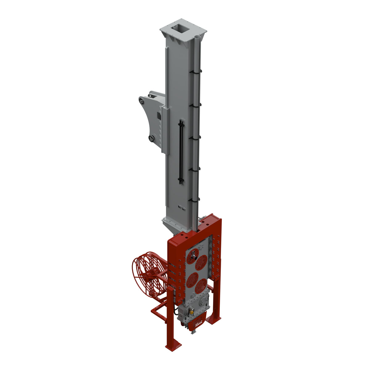
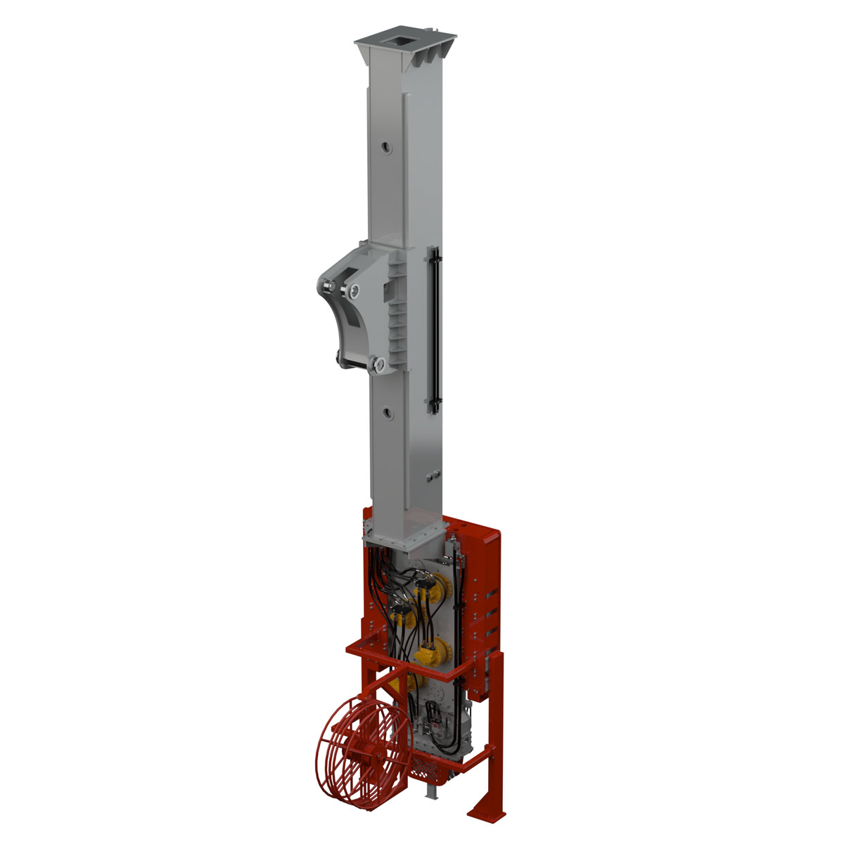
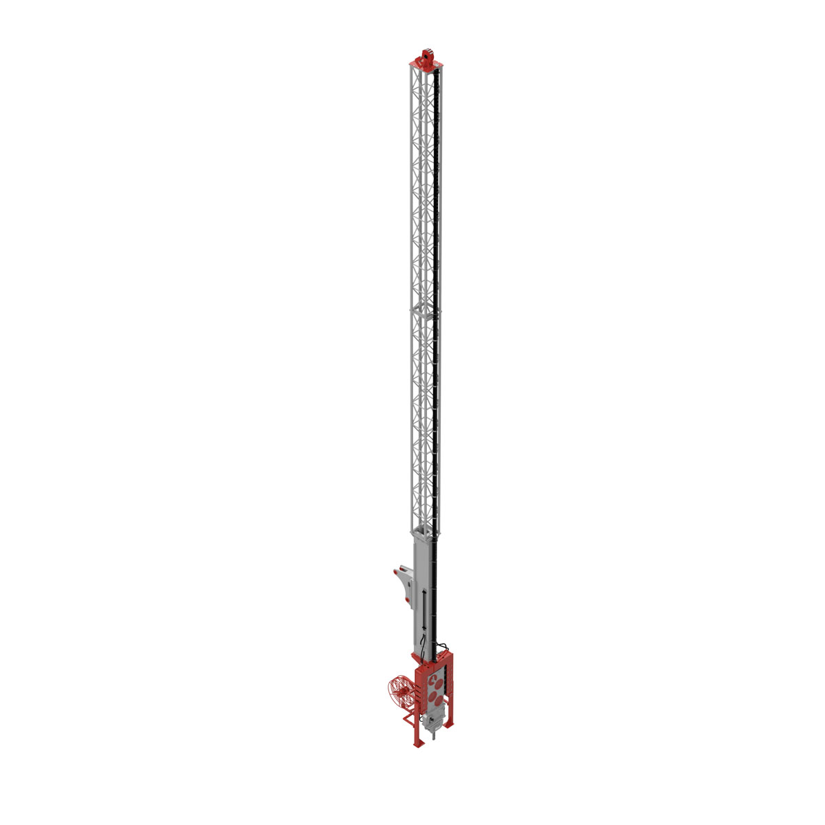
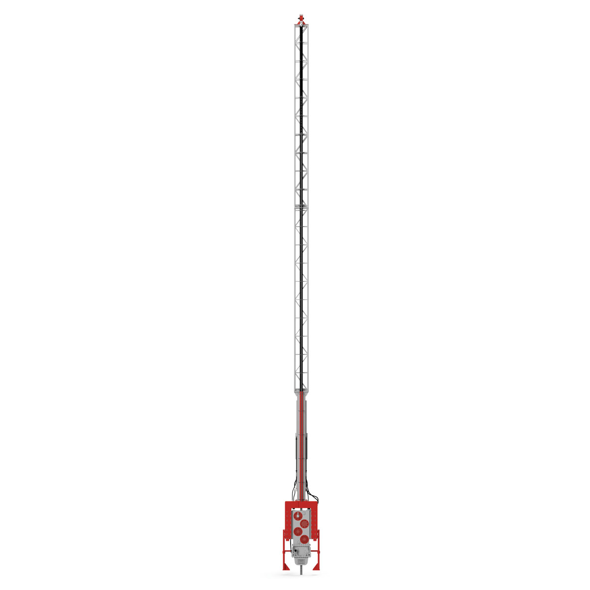
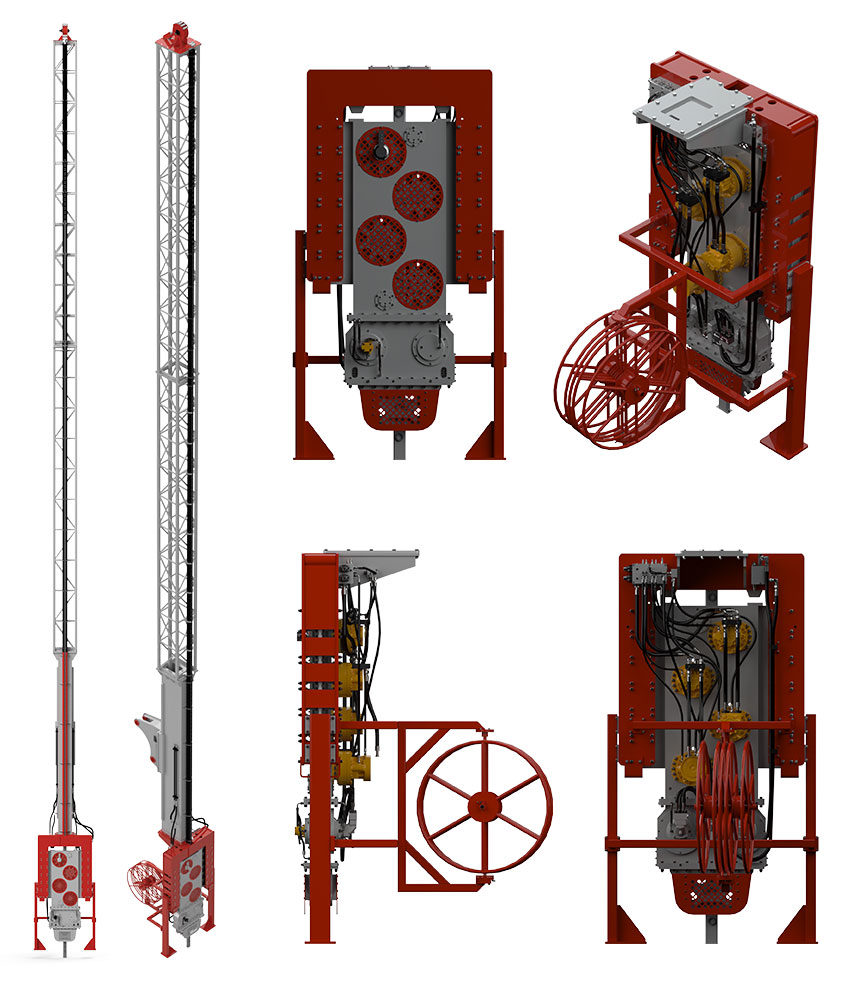
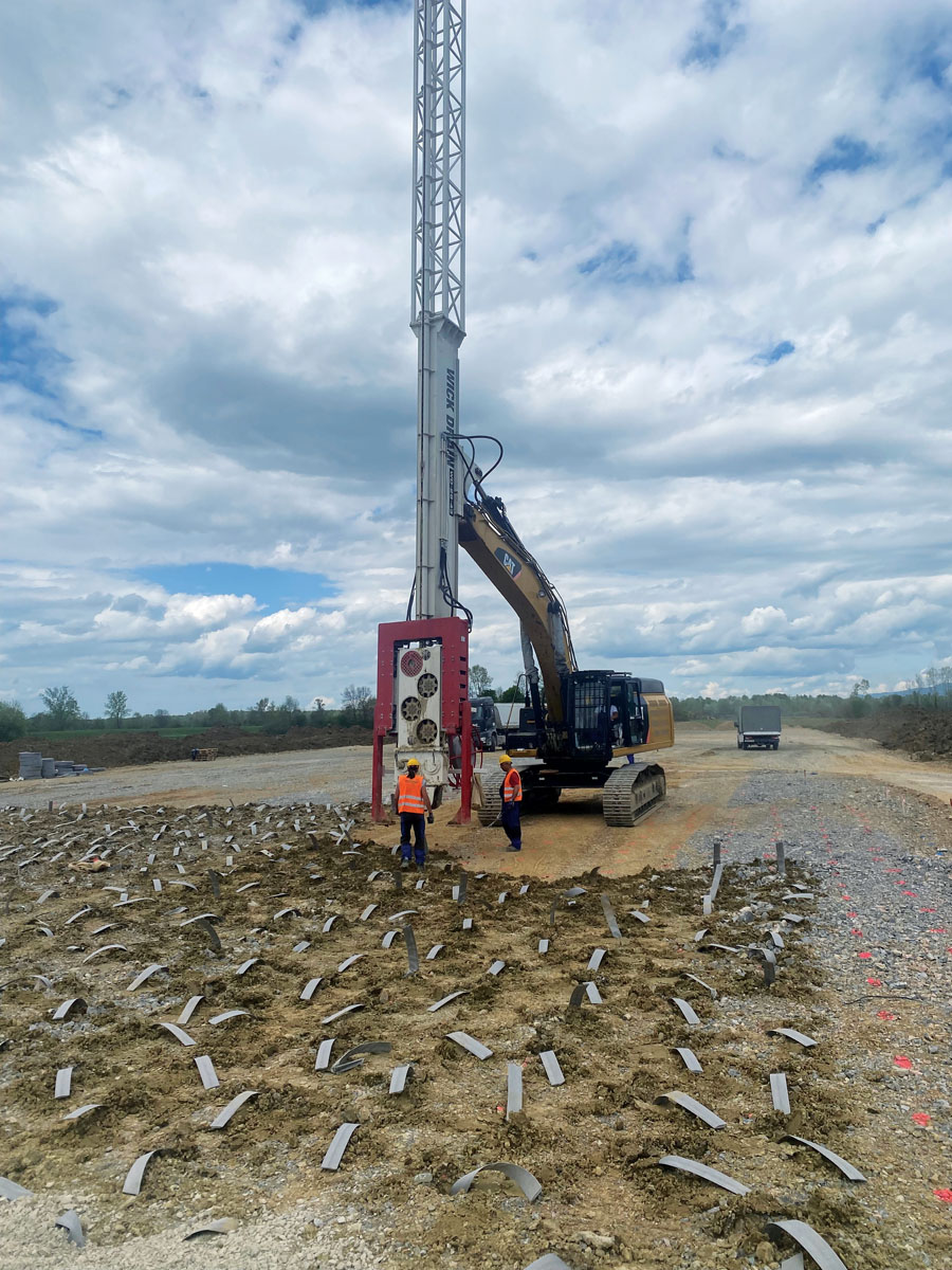
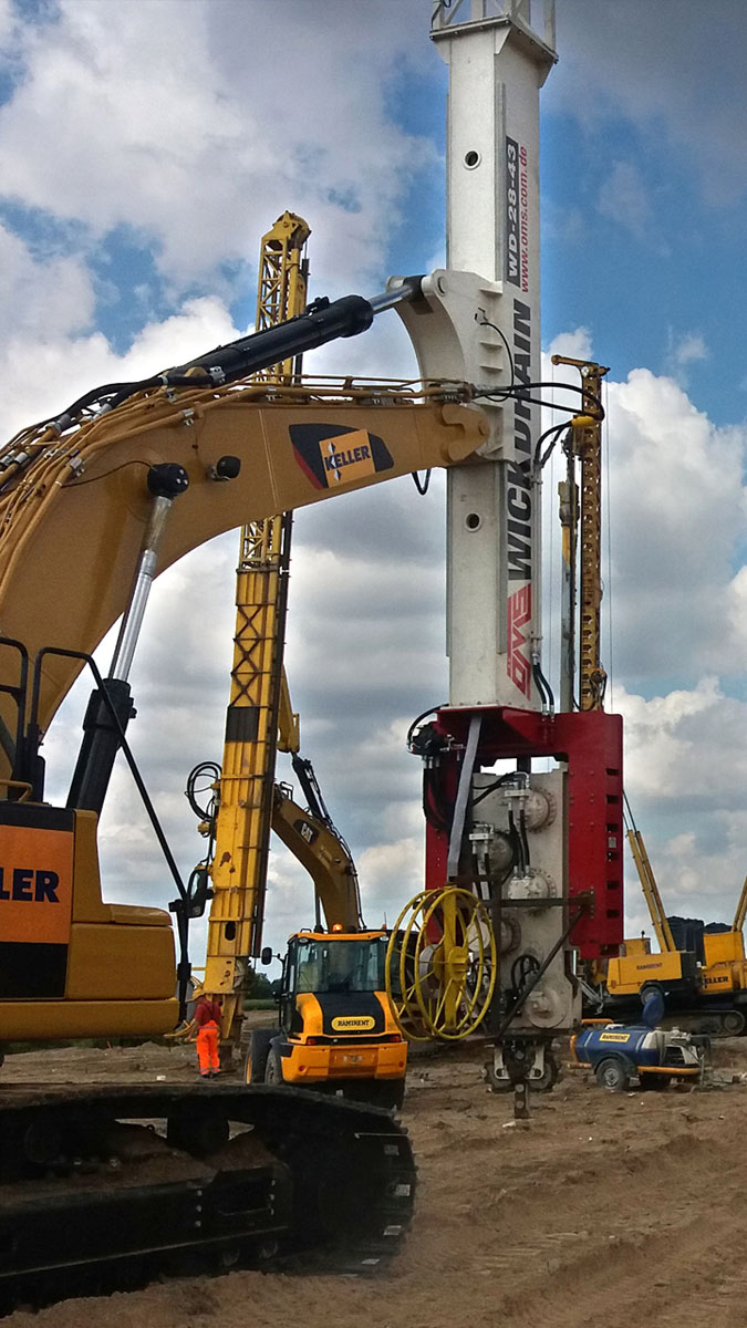
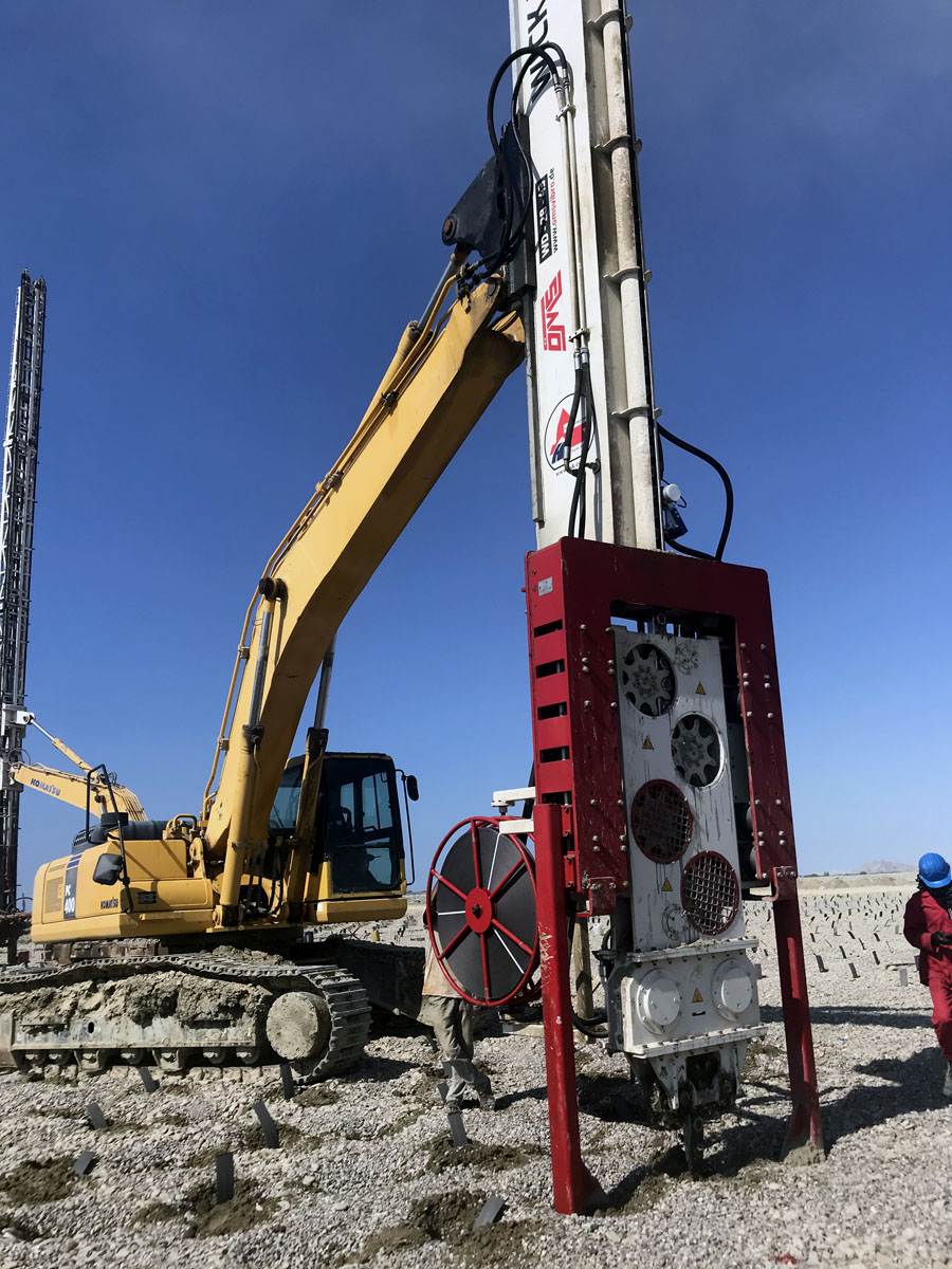
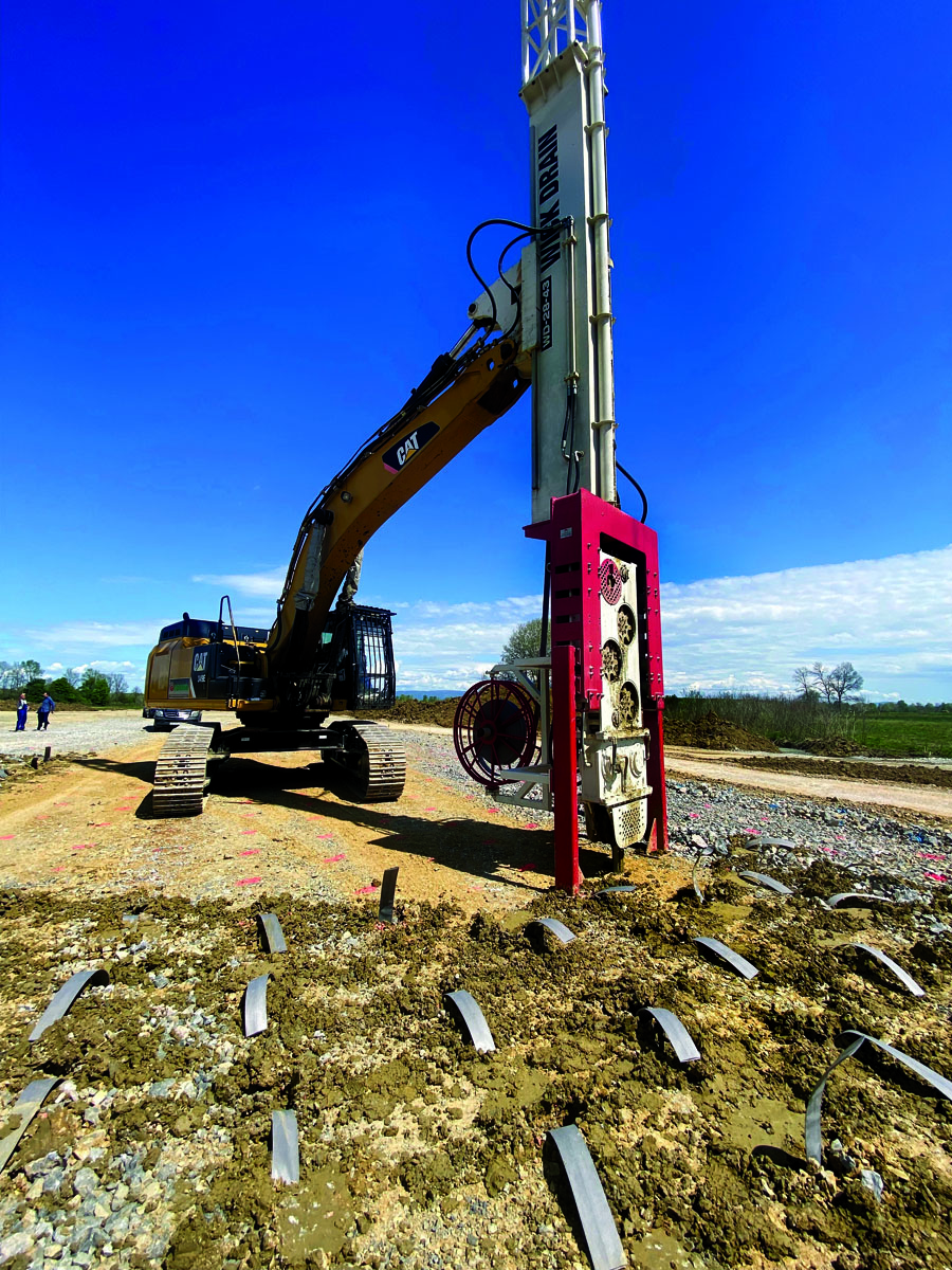
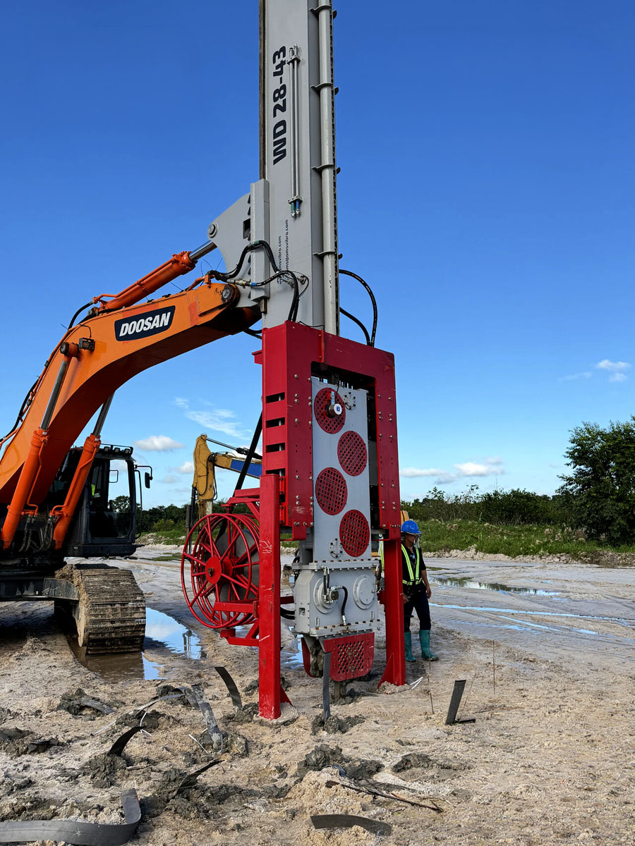
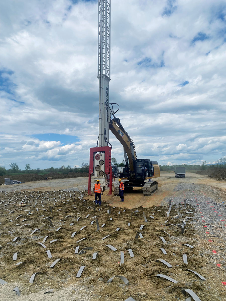
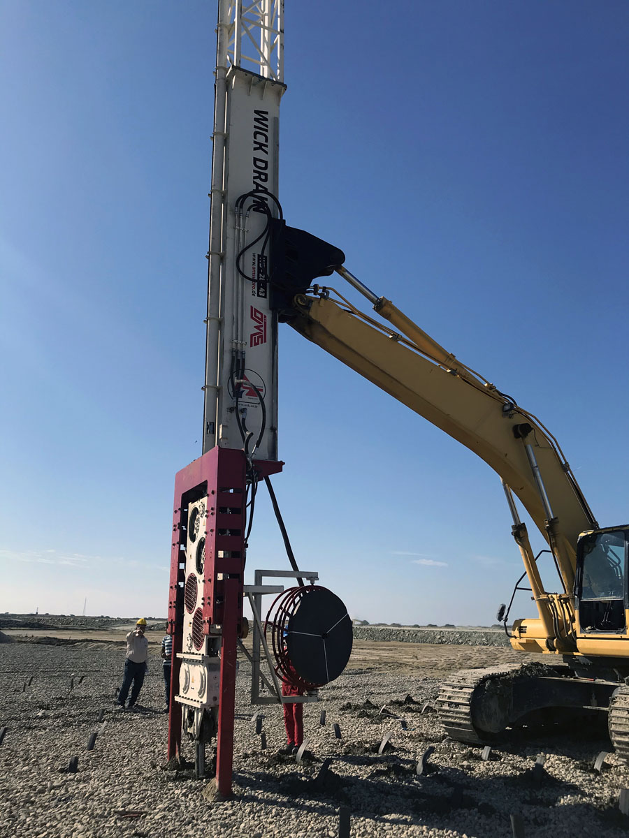
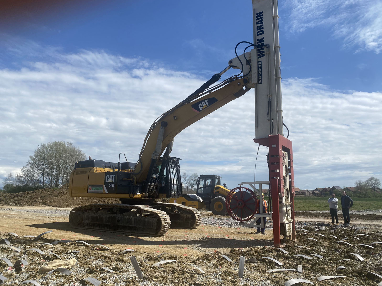
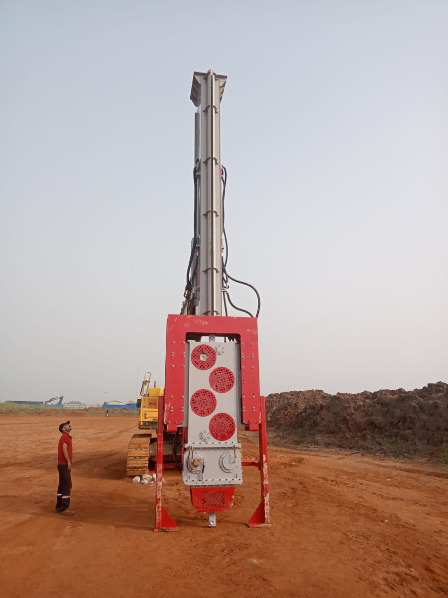
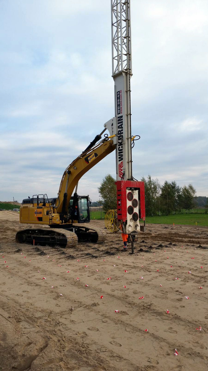
The OMS WD 28-43 Wick Drain Installation Equipment combines a mechanically driven PVD insertion system with a high-frequency vibro driver. By applying static crowd force and dynamic force together, the machine is designed to install prefabricated vertical drains efficiently through varying soil layers.
How Prefabricated Vertical Drains Accelerate Soil Consolidation
In low-permeability soils, pore water may require a long time to dissipate naturally. This delays the increase in effective stress and extends the period during which settlement can continue.
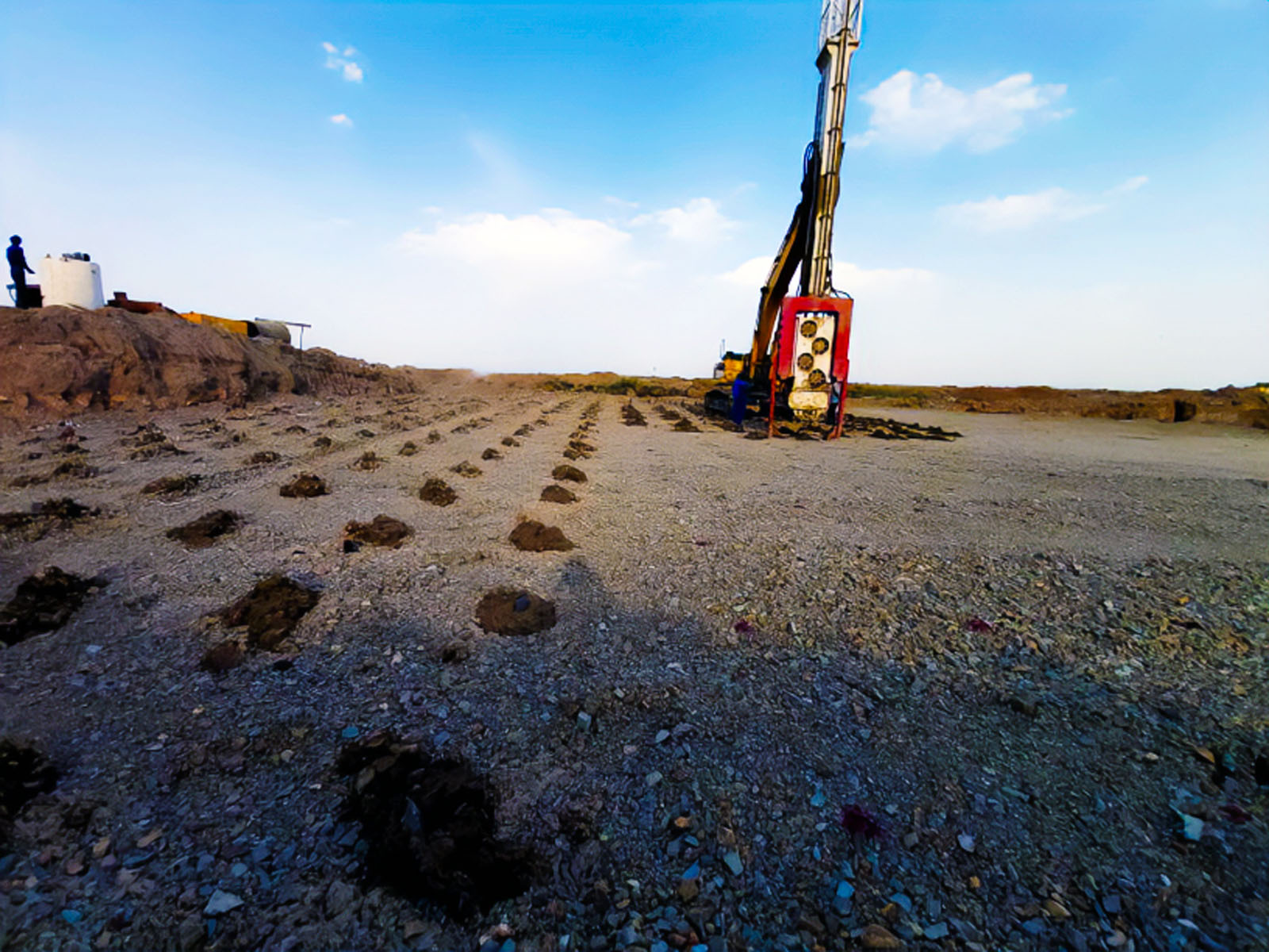
Wick drains provide shorter, controlled drainage paths. The drains collect water from the surrounding soil and convey it vertically toward the surface. A drainage blanket placed at ground level then helps distribute and discharge the rising water.
The consolidation programme normally includes three coordinated elements:
- A project-specific PVD installation pattern
- A surface drainage blanket
- Surcharge or earth loading defined by the geotechnical design
The wick drains do not replace the need for project-specific soil analysis. Drain depth, spacing, pattern and preload requirements must be determined from the soil profile, groundwater conditions, target settlement and allowable consolidation period.
Engineering Principle of the OMS WD 28-43
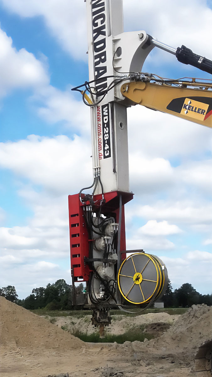
The WD 28-43 uses a mandrel to carry the prefabricated vertical drain to the required depth. Its drive system applies static insertion force, while the integrated vibro driver introduces dynamic force to reduce penetration resistance.
These values define the machine’s available installation capacity. Actual penetration rate and achievable installation depth remain dependent on the soil stratigraphy, mandrel configuration, hydraulic supply, drain material and project requirements.
| Technical Parameter | WD 28-43 |
|---|---|
| Static crowd force | 276 kN |
| Dynamic force | 435 kN |
| Combined force | 711 kN |
| Operating frequency | 2,500 rpm |
| Maximum hydraulic pressure | 350 bar |
| Maximum vibro oil flow | 200 l/min |
| Maximum wick drive oil flow | 506 l/min |
| Maximum mandrel speed | 100 m/min |
| Recommended excavator working weight | 45–60 tonnes |
| Suspended weight | 3,077 kg |
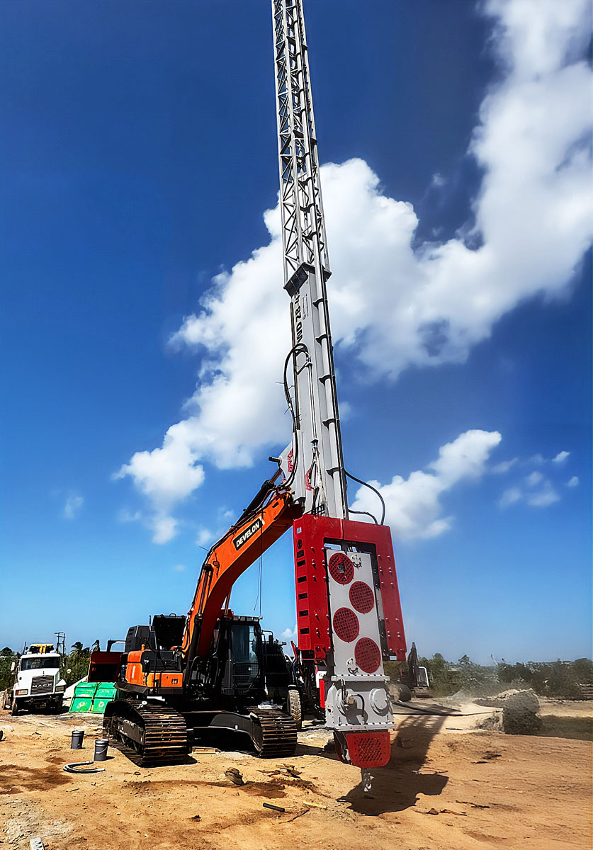
Combined Static and Dynamic Force
Equipment using only static crowd force may experience reduced penetration performance when the mandrel encounters resistant or variable layers. The WD 28-43 combines 276 kN of static crowd force with 435 kN of dynamic force, producing a total combined force of 711 kN.
The static system controls mandrel insertion and extraction. The vibro driver assists penetration by reducing resistance around the mandrel. This combined operating principle supports a more consistent installation process where soil resistance changes with depth.
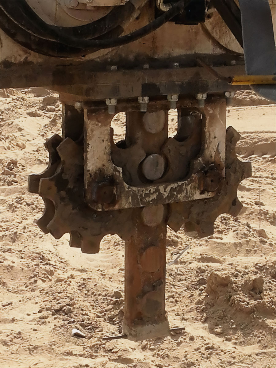
Sprocket Drive and Mandrel Control
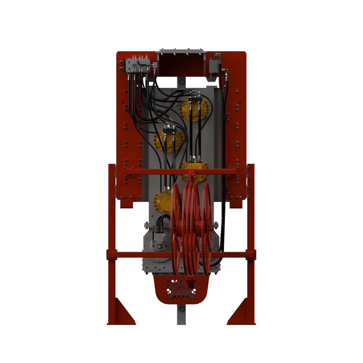
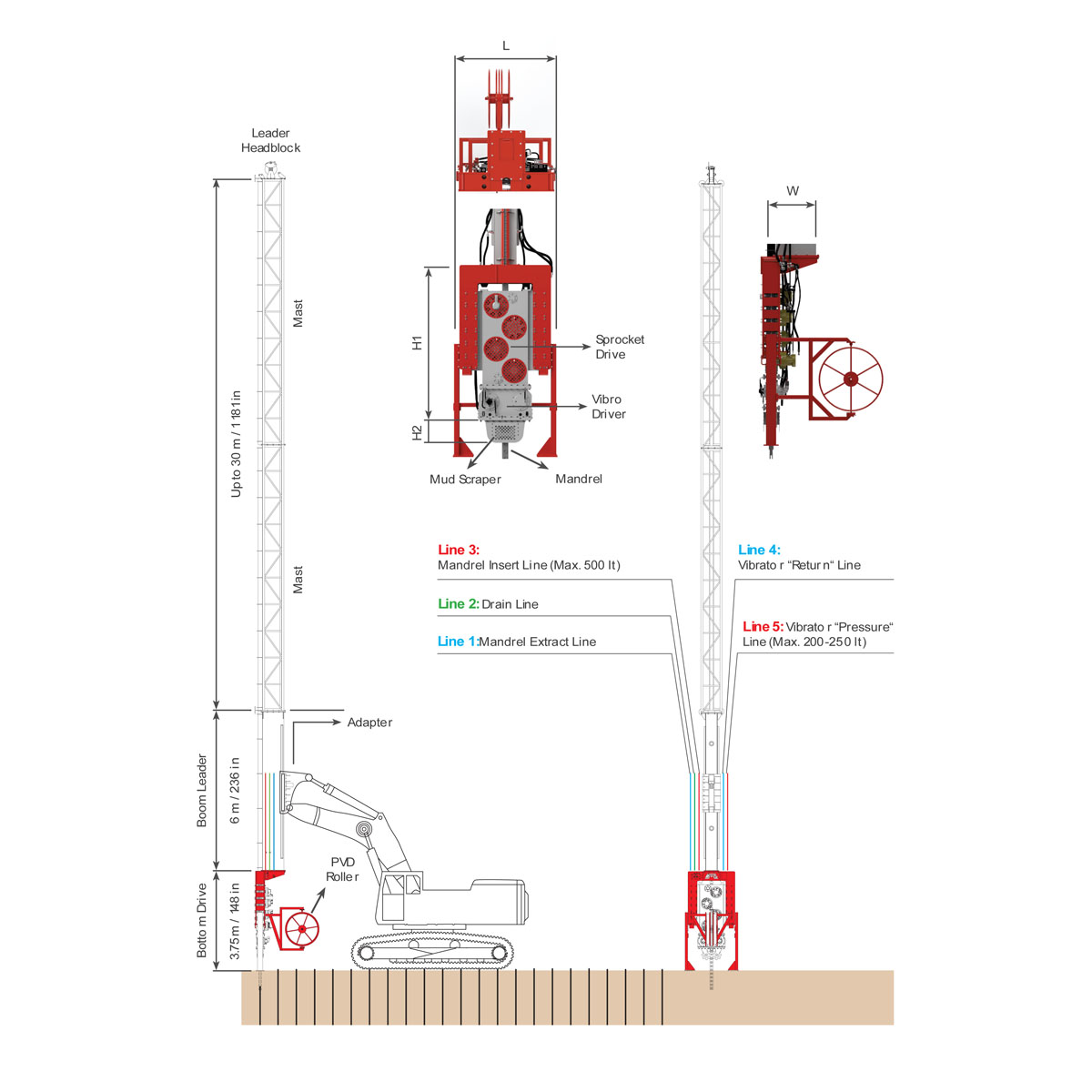
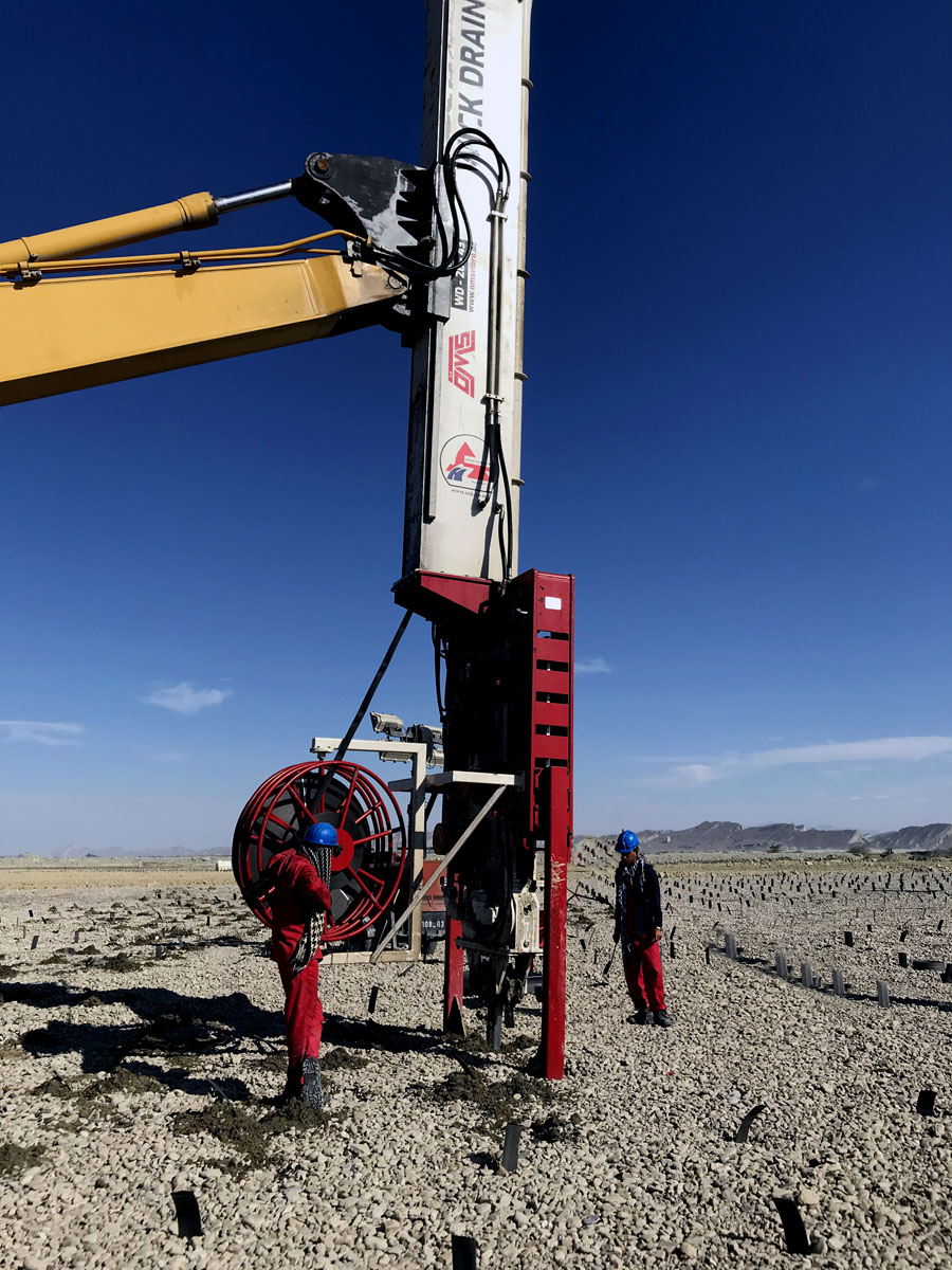
Hydromotors and sprocket gears drive the mandrel along the mast. The drive arrangement controls both insertion and extraction, while the mandrel guides the PVD material into the soil.
The maximum mandrel speed is 100 m/min. This is the machine’s rated maximum value rather than a guaranteed production rate. Site productivity must be evaluated according to installation depth, repositioning time, soil resistance, drain cutting and anchoring, equipment setup and operator workflow.
Vibro Driver
The integrated high frequency vibro driver operates at 2,500 rpm. It supplements the static drive force when additional penetration assistance is required.
The operating mode must always correspond to the actual soil conditions and approved installation procedure. Excessive or uncontrolled vibration can affect alignment, drain continuity and surrounding ground behaviour. Site-specific operating parameters should therefore be established by the responsible project team.
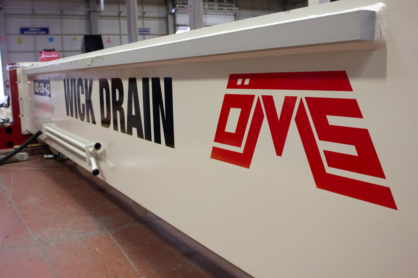
Main Components of the WD 28-43 System
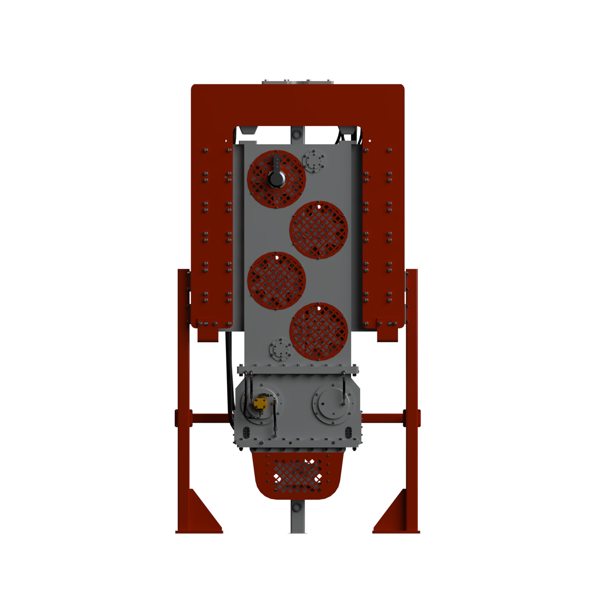
The OMS WD 28-43 configuration includes the principal systems required to store, guide and install PVD material:
The mud scraper helps remove adhered soil from the mandrel during extraction. This supports cleaner operation around the drive system and reduces material accumulation during repeated installation cycles.
Mast Configuration and Excavator Integration
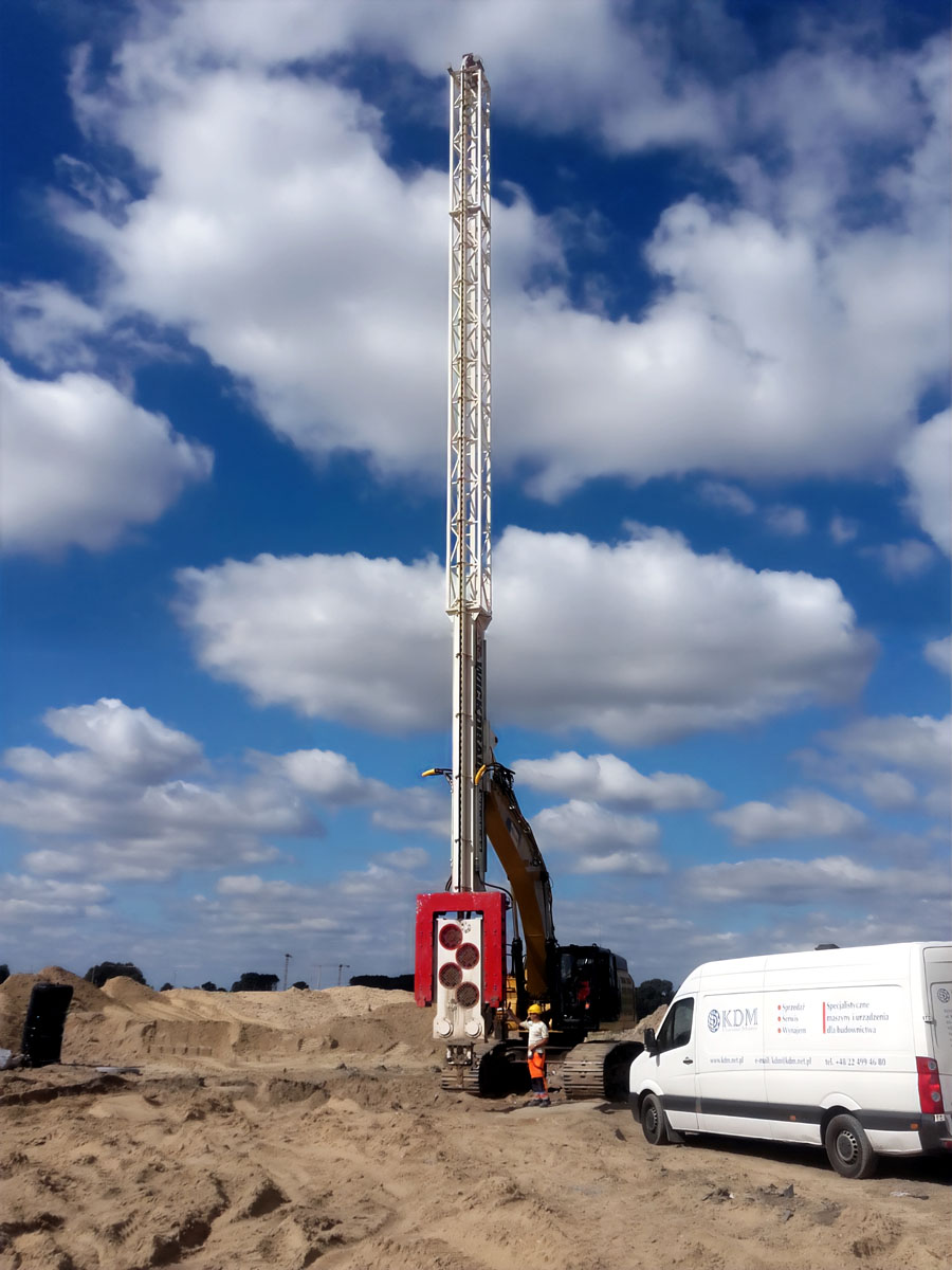
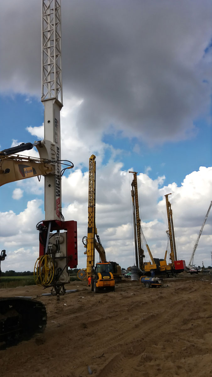
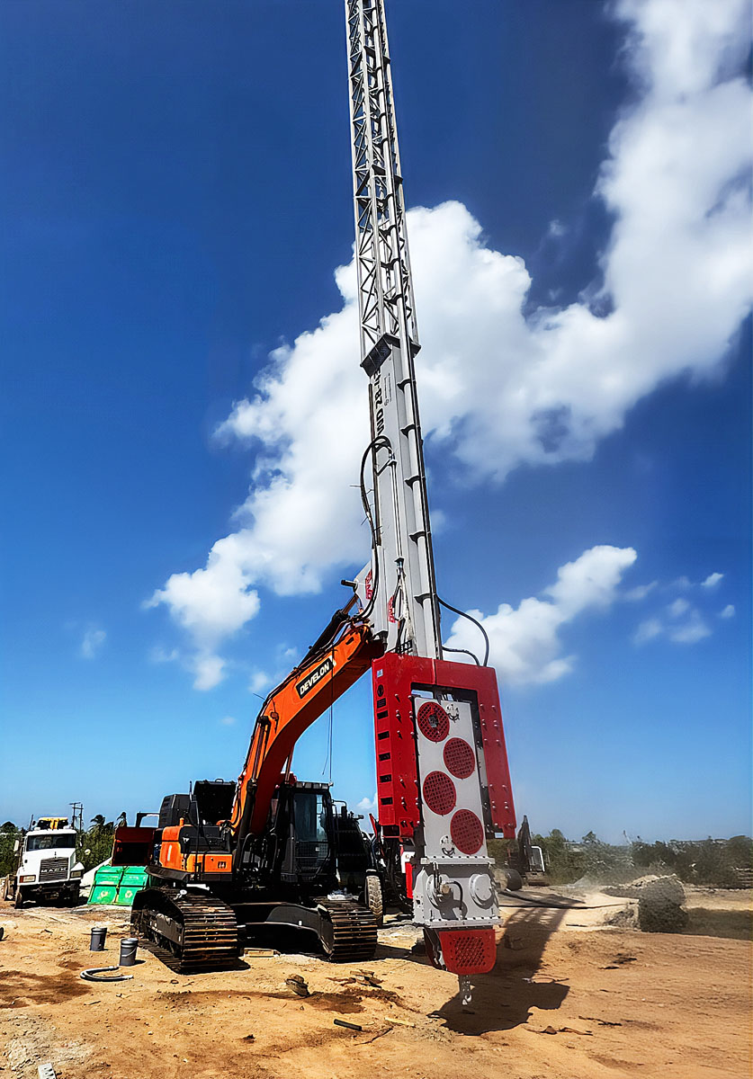
The WD 28-43 is configured as an excavator-supported mast system. The OMS catalogue shows a mast arrangement of up to 30 m, together with a 6 m boom leader and a 3.75 m bottom drive section.
The mast provides the vertical guide path needed to control the mandrel over the selected installation depth. Its configuration must be matched to:
OMS recommends an excavator working weight between 45 and 60 tonnes for the WD 28-43. Excavator selection must not be based on operating weight alone. Hydraulic capacity, boom geometry, lifting chart, stability and connection design must also be verified for the intended mast configuration.
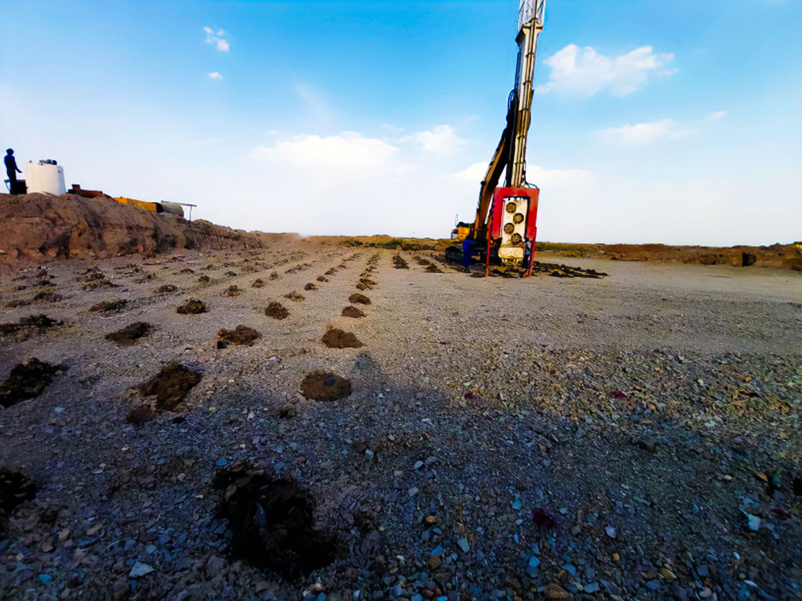
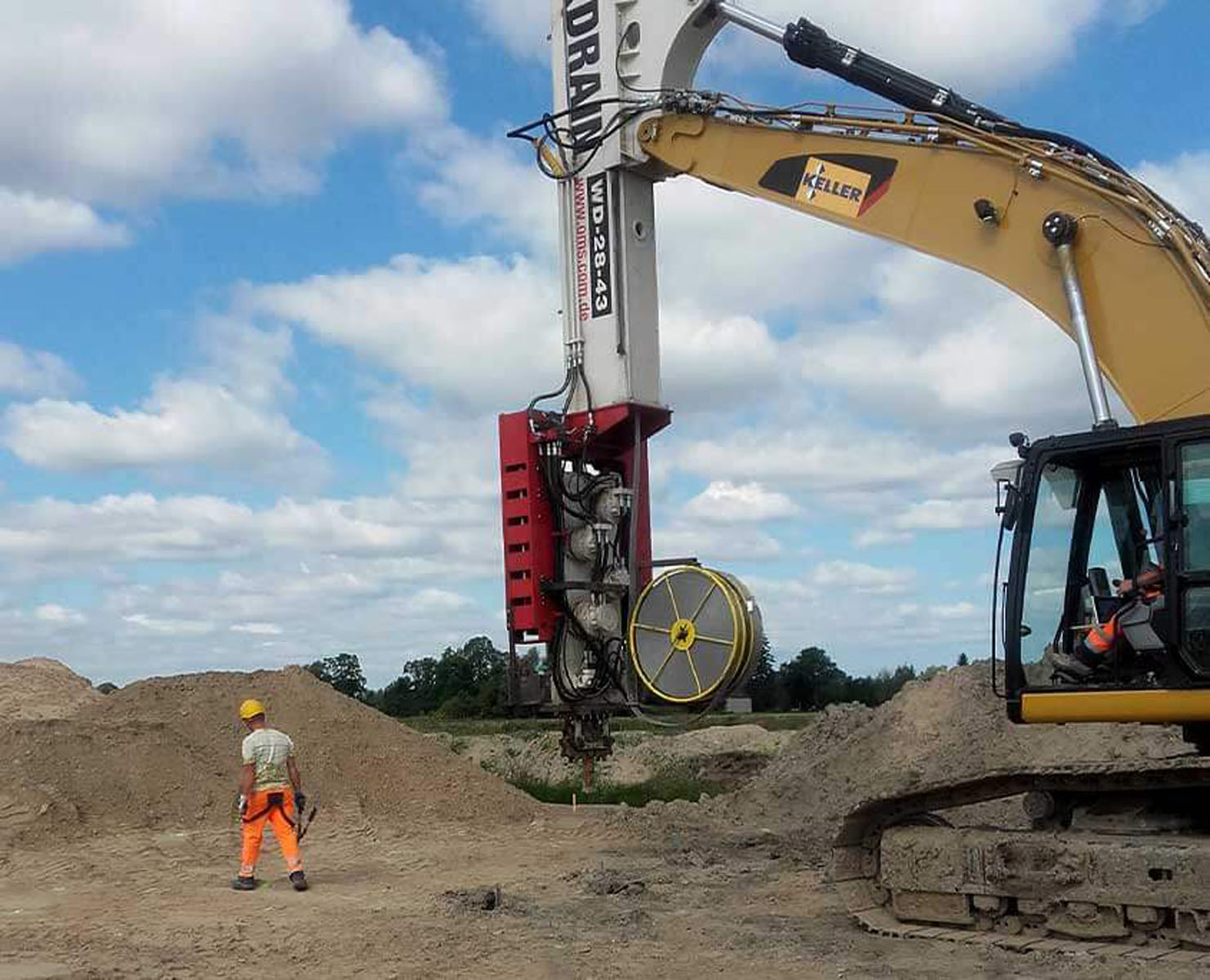
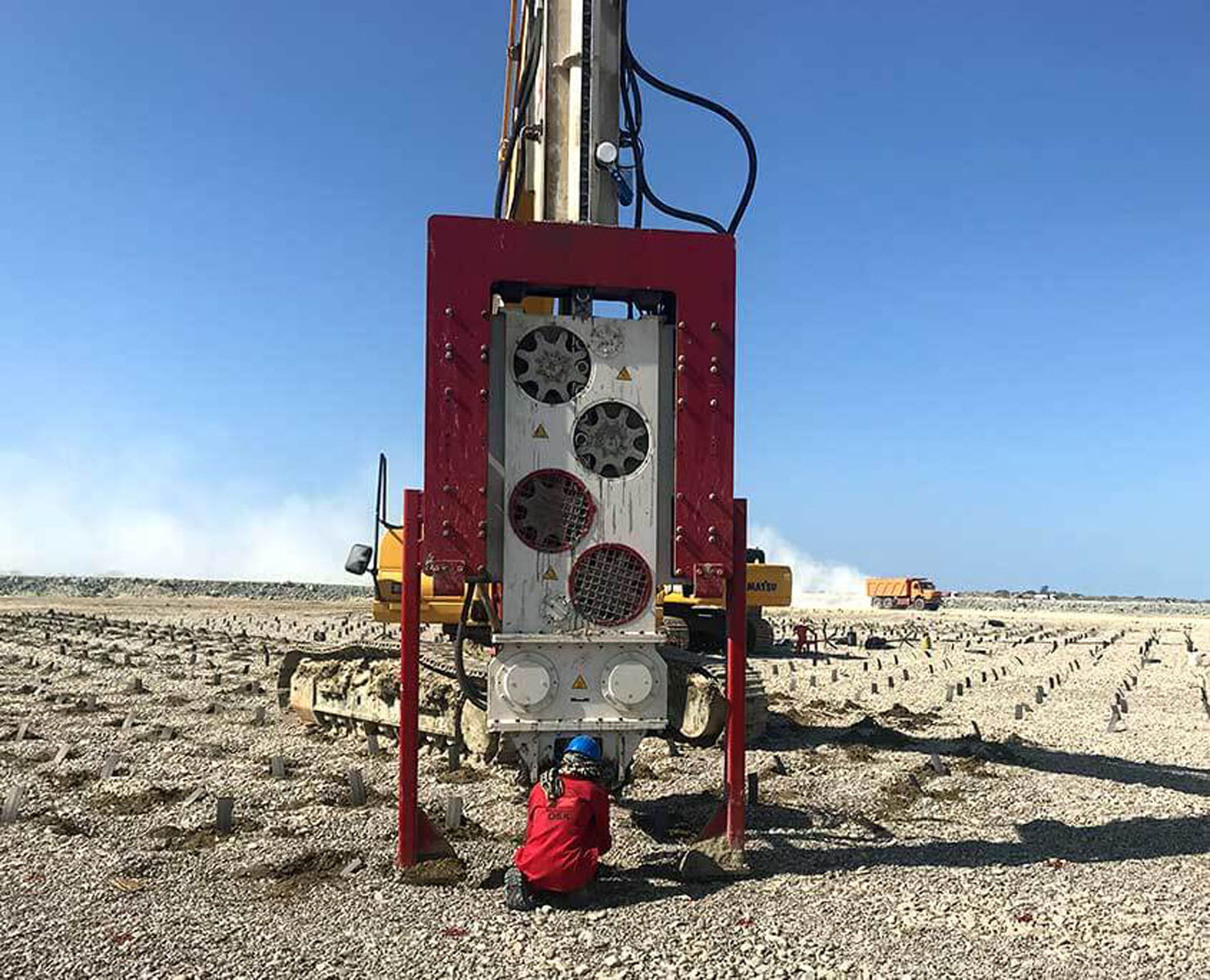
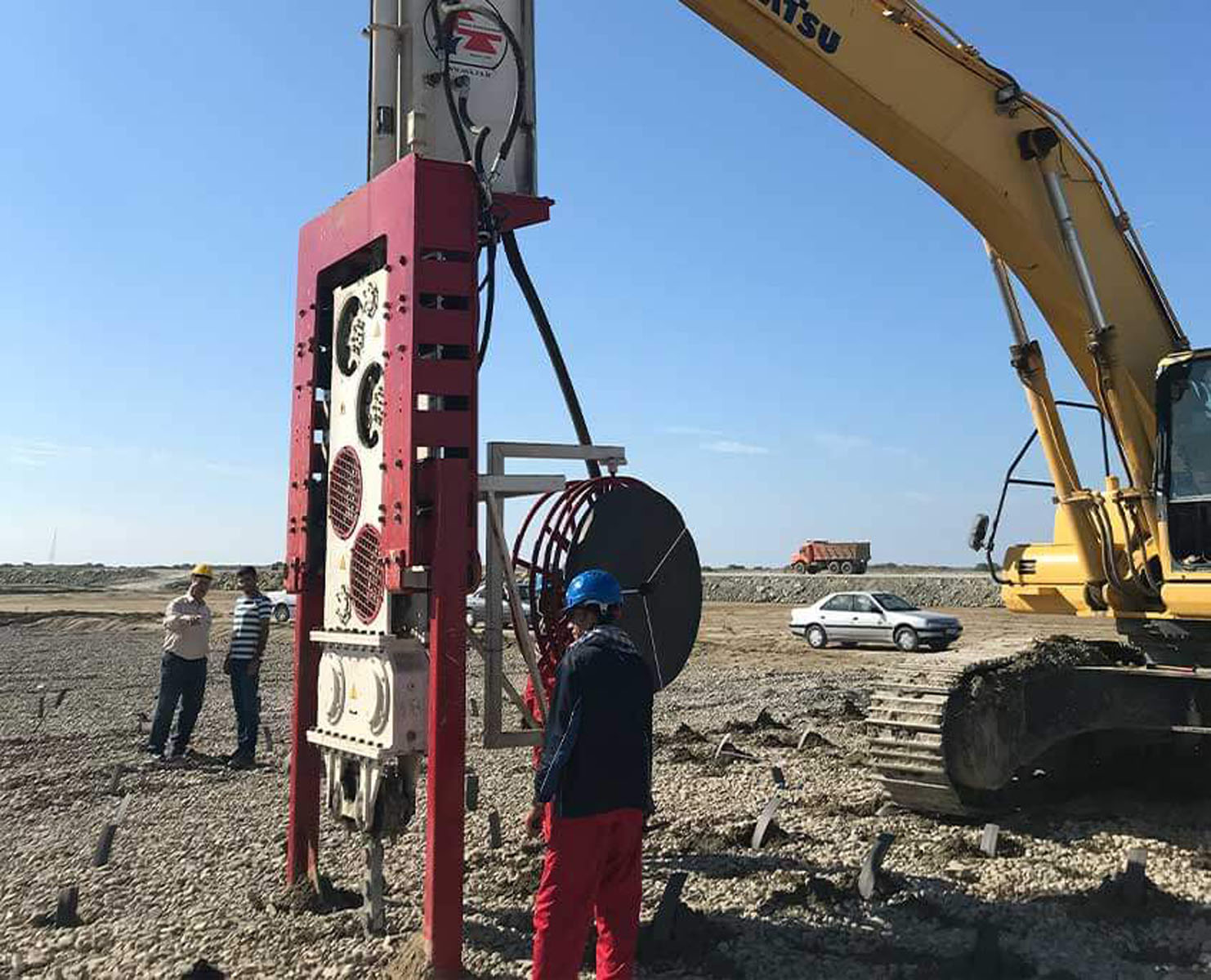
How Wick Drains Are Installed with the WD 28-43
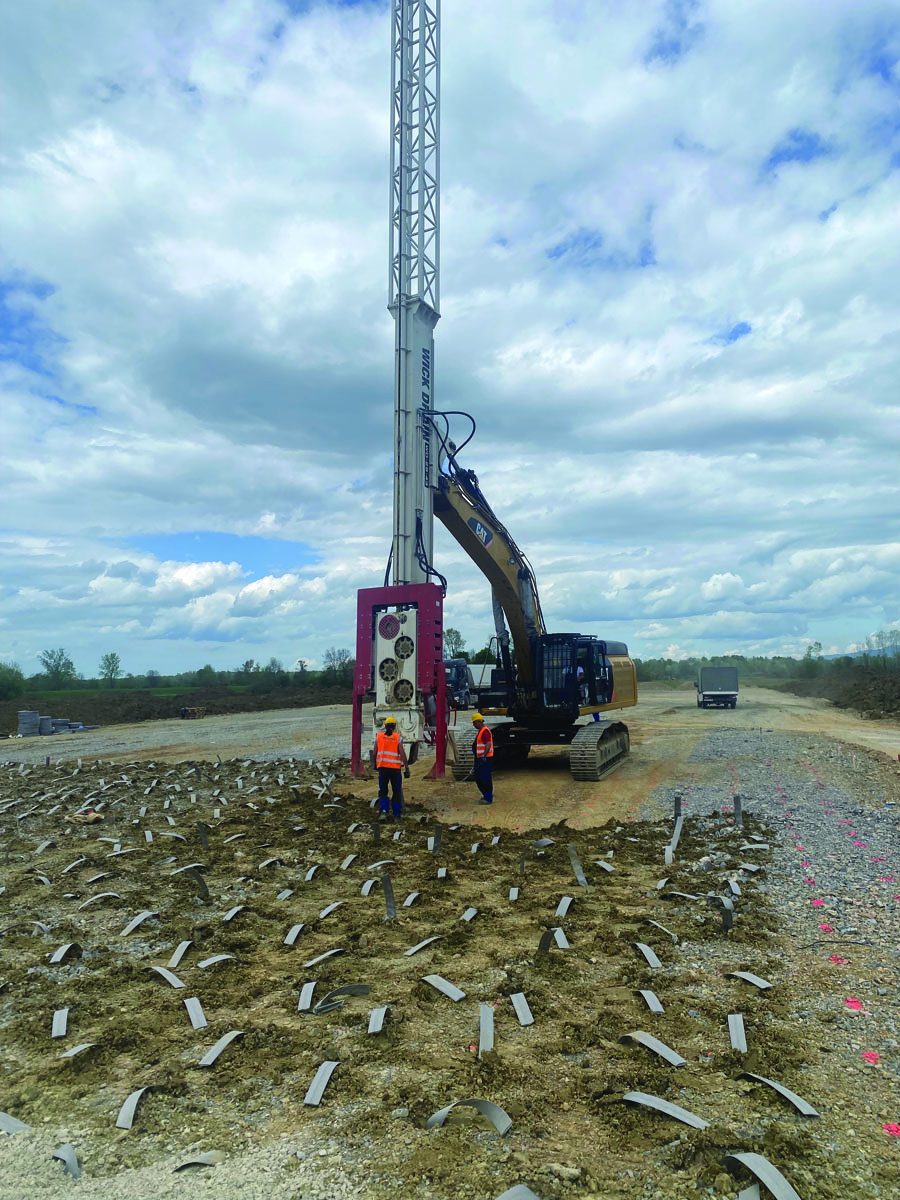
The installation sequence begins with geotechnical design and site preparation. Drain spacing, installation depth, drainage pattern and preload requirements must be defined before field operations start.
Application Areas for the WD 28-43
The WD 28-43 can be considered for projects requiring accelerated consolidation of soft and cohesive ground, including:
The final equipment configuration must be based on the project’s geotechnical data rather than the application category alone.
Engineering Criteria for Equipment Selection
Before configuring the WD 28-43, the project team should evaluate:
The final equipment configuration must be based on the project’s geotechnical data rather than the application category alone.
Frequently Asked Questions
A PVD creates a shortened drainage path through soft, water-bearing soil. Together with the designed surcharge and drainage blanket, it helps accelerate pore-water dissipation and consolidation.
Static force controls mandrel insertion and extraction, while dynamic force assists penetration through resistant or variable layers. The WD 28-43 provides a combined force of 711 kN.
The OMS configuration includes a mast arrangement of up to 30 m. The actual installation depth must be verified according to mast configuration, soil profile, mandrel design, excavator capacity and project requirements.
The recommended excavator working weight is 45–60 tonnes. Hydraulic capacity, lifting geometry, stability and connection suitability must also be checked.
No. The rated maximum mandrel speed is 100 m/min. Actual production depends on installation depth, soil resistance, equipment positioning, drain handling, anchoring and site workflow.
Project-specific quality records may include drain location, installation depth, verticality, penetration time, extraction behaviour, drain consumption, obstructions and any interrupted or rejected installation point.
OMS Vibro Value Propositions
The OMS WD 28-43 provides a combined mechanical and vibratory solution for prefabricated vertical drain installation. Its 276 kN static force, 435 kN dynamic force and excavator-supported mast configuration help address variable penetration resistance while maintaining controlled mandrel movement.
Successful soft soil consolidation still requires an integrated engineering approach. Soil conditions, drain spacing, installation depth, drainage blanket, surcharge loading, monitoring requirements and equipment configuration must be evaluated together.
Contact the OMS Vibro technical team to review the appropriate WD 28-43 mast, excavator and hydraulic configuration for your wick drain project.
Get professional advice to find the most efficient equipment for your application.